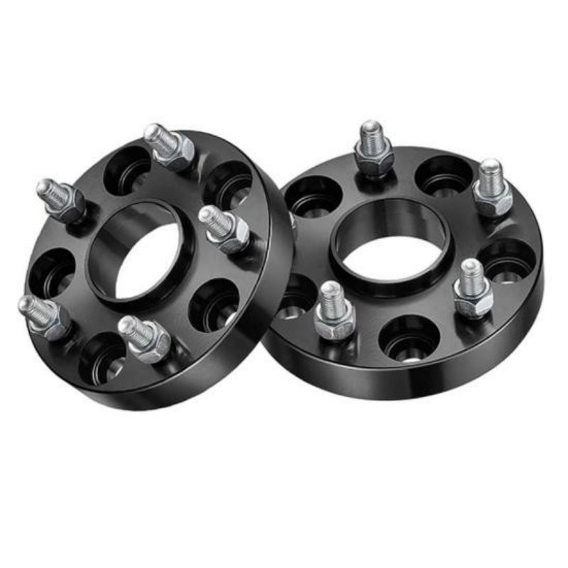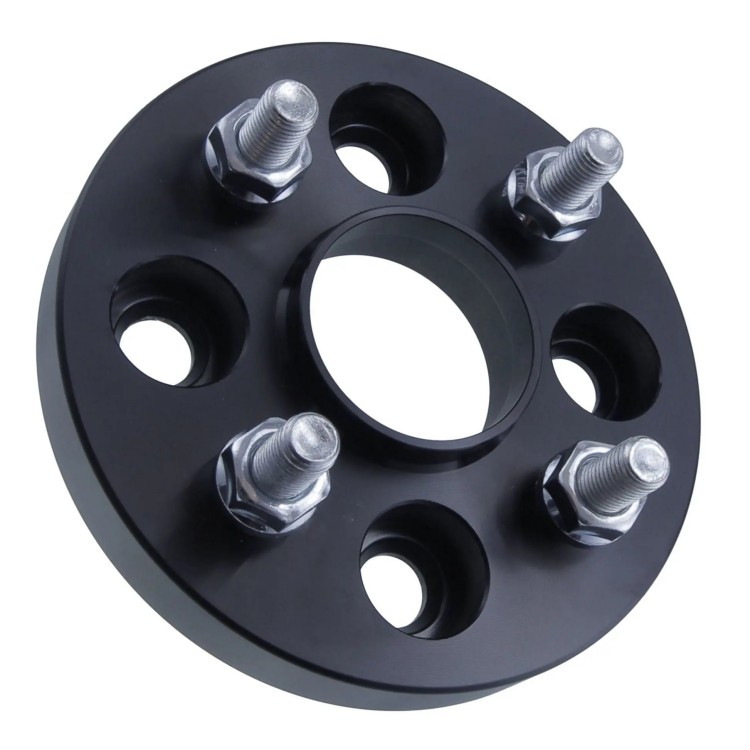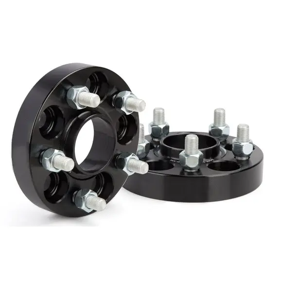

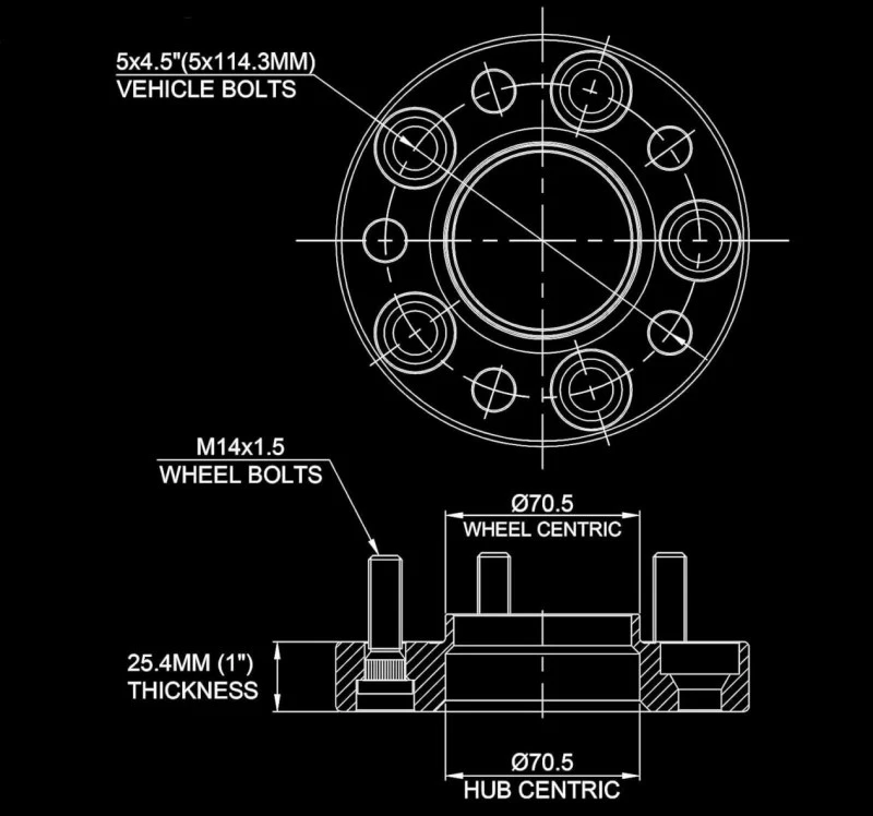
Measure outside clearance with a straightedge, then verify the inside and the mounting interfaces. Record the wheel and tire, PCD, vehicle hub, wheel center bore, offset, hardware and available wheel-pocket depth. Select a thickness below the static outer gap and confirm the complete assembly on the vehicle.
A spacer can move a wheel outward by its nominal thickness, but that does not mean every available millimeter should be used. A parked vehicle shows only one position. Tire shape, steering lock, suspension travel, wheel back-pad geometry and brake hardware can reduce the clearance that looked available during the first measurement.
Use this page as the measuring spoke in our wheel-spacer cluster. For the complete specification sequence, start with the wheel spacer fitment guide. For product-type selection, see slip-on vs bolt-on wheel spacers.
Start with the current wheel-and-tire baseline
Measure the vehicle in its normal operating configuration: correct tire pressure, the wheels fully seated, and the vehicle resting at normal ride height on a level surface. Record any suspension, brake or body changes before reaching for a spacer.
| Record first | Where to find it | Why it changes the result |
|---|---|---|
| Wheel width and offset | Wheel marking, drawing or manufacturer data | Defines the wheel's present inner and outer position |
| Tire size and actual section width | Sidewall plus physical inspection | The tire may be the closest point to the fender or suspension |
| Vehicle, year, trim and axle | Vehicle records and service data | Brake, hub and suspension packages may differ |
| PCD and center diameters | Verified application data or accurate measurement | Controls whether the part can align and locate |
| Fastener type | Stud or bolt, thread, seat and usable length | Controls attachment and thread engagement |
Useful tools include a rigid straightedge, millimeter ruler, vernier caliper, depth gauge and a way to record photos and dimensions. Do not crawl under or work around an unsupported vehicle. Clearance checks that require lifting, steering or suspension compression belong with a properly equipped technician.
Measure the outer fender gap with a straightedge
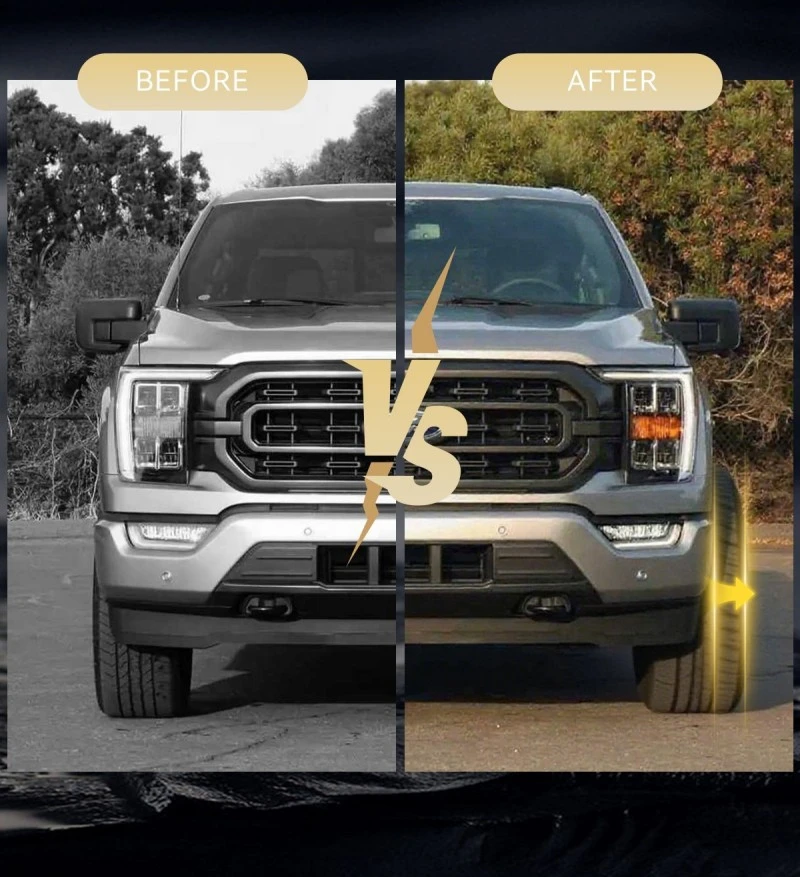
Eibach's official measuring method places a straightedge against the closest outer fender point and measures from the wheel or tire's outermost point to that line. Eibach recommends choosing a spacer slightly thinner than the measured flush-to-fender distance. See the Eibach PRO-SPACER measuring guide.
- Find the least-clearance point. It is often near the middle of the wheel arch, but inspect the full opening.
- Hold the straightedge vertically. It should represent the fender boundary without leaning inward or outward.
- Measure horizontally. Measure from the tire sidewall or wheel face—whichever projects farther—to the straightedge.
- Repeat front and rear. The two axles may use different wheels, body clearances or target positions.
- Record the smallest result. Use the limiting side, not the largest gap, as the starting point.
Inspect the inside before deciding the thickness
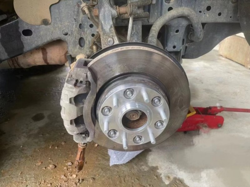
The outward move may create caliper or suspension clearance, yet it also changes where the tire travels relative to the fender and liner. Check the brake caliper, upright, control arms, spring or coilover, inner liner, hoses, wiring and any balance weights. The closest component may differ from front to rear.
Turn the steering from lock to lock where applicable and inspect the complete path. Dynamic verification also needs suspension compression and realistic loading. Eibach's installation instructions call for checking tire/fender clearance, brake lines and sensor components after installation; the wheel must rotate freely before road testing.
Translate the gap into a conservative thickness
outer position change ≈ spacer thicknessA 12 mm spacer moves the same wheel outward by approximately 12 mm.
If the smallest measured outer gap is 18 mm, 18 mm is not automatically the correct part. It is the static distance to the line you measured. The selected thickness needs a margin for tire deflection, steering movement, suspension compression and measurement uncertainty.
The same thickness also reduces effective wheel offset. A wheel marked ET45 with a 12 mm spacer sits approximately like ET33 with the same wheel. Use the formula as a position check, not as final application approval.
A tire that is visually flush while parked may contact the body when turning, loaded or compressed. If dynamic clearance cannot be checked, do not increase the spacer thickness.
Measure the hub, wheel bore and locating lip
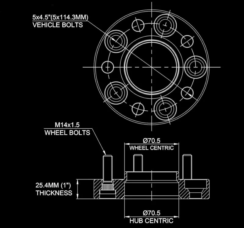
A hub-centric spacer has two fitment sides. The inner bore locates over the vehicle hub; the outer lip locates the wheel or its approved centering arrangement. Measure or verify:
- vehicle hub outside diameter;
- hub-lip height available for the spacer;
- base chamfer, radius and any protruding retention hardware;
- wheel center bore;
- wheel back-pad recess and the depth available for the spacer lip.
A caliper reading of the nominal diameter is not enough if a chamfer or radius prevents the spacer from reaching the mounting face. Dry-fit both interfaces and reject any visible gap or rocking.
Measure fasteners after the spacer system is known
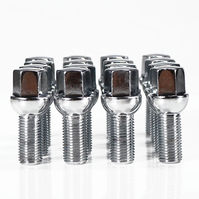
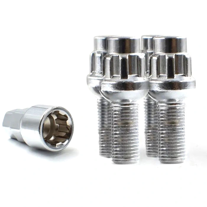
For a slip-on system that requires longer wheel bolts, H&R states that the replacement bolt should be longer than the original by the spacer width. The head or seat must remain correct for the wheel. Its TRAK+ application note also gives thread-specific engagement values rather than one universal turn count.
| Hardware field | Measure or verify | Common mistake |
|---|---|---|
| Thread | Diameter and pitch | Ordering by wrench size |
| Seat | Conical, ball radius or flat/shank system | Matching thread but not the wheel seat |
| Usable length | Length that actually enters the hub or nut | Comparing total bolt length with different head designs |
| Stud knurl | Knurl diameter and length for press-in studs | Assuming every longer stud fits the hub |
For bolt-on spacers, measure stud projection and wheel pockets
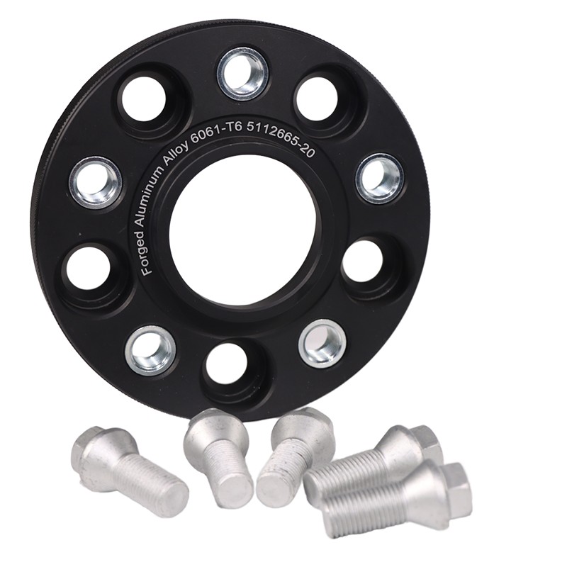
A bolt-on spacer creates a second attachment interface. After the spacer is fastened to the hub, any original stud or bolt end that projects beyond the spacer face must fit inside a suitable recess in the wheel back pad. Eibach notes that some bolt-on systems require alloy wheels with pockets or cut-outs so the wheel can sit flush.
required pocket depth > remaining hardware projectionInclude a practical clearance margin; contact is not acceptable.
Measure projection from the finished spacer face, then measure the usable pocket depth and diameter in the wheel. Check every pocket because wheel castings and machining can vary. Do not grind the wheel or alter studs unless the exact manufacturer-approved application explicitly requires and permits it.

Use one measurement worksheet per wheel package
| Field | Front | Rear | Evidence |
|---|---|---|---|
| Wheel size / offset | _____ | _____ | Wheel marking or drawing |
| Tire size / closest point | _____ | _____ | Sidewall and photo |
| Static outer gap | _____ mm | _____ mm | Straightedge measurement |
| PCD / hub diameter | _____ | _____ | Service data or measurement |
| Wheel center bore | _____ mm | _____ mm | Wheel drawing or caliper |
| Thread / seat / usable length | _____ | _____ | Original hardware comparison |
| Stud projection / pocket depth | _____ | _____ | Depth measurement, if applicable |
| Proposed spacer thickness | _____ mm | _____ mm | Approved application drawing |
Send the worksheet with photos and a marked drawing when requesting a custom or wholesale quote. J&W publishes custom PCD, center-bore, thickness, finish and packaging options on its wheel spacer supplier page; the order drawing should control the exact project.
Stop the measurement process when evidence is missing
Do not proceed when the PCD is assumed, the spacer cannot sit flat, the hub or wheel bore is uncertain, a tire already rubs, the required pocket depth is unavailable, or conflicting torque and hardware instructions have not been resolved. A qualified installer should verify the final assembly and follow the vehicle, wheel and spacer instructions.
Wheel spacer measurement FAQ
How do you measure the wheel spacer thickness you need?
Place a straightedge vertically against the closest outer fender point, then measure horizontally from the tire or wheel's outermost point to the straightedge. Treat that distance as an upper visual limit, choose a smaller spacer, and verify inner, steering and suspension clearance on the actual vehicle.
Is the fender gap the same as the correct spacer thickness?
No. The static fender gap does not include tire deflection, steering movement, suspension compression or differences between the front and rear axles. It is one input, not final fitment approval.
What hub measurements are needed for a hub-centric spacer?
Measure or verify the vehicle hub diameter, hub-lip height and base chamfer, then confirm the wheel center bore and available lip engagement. A supplier needs both the vehicle-side bore and wheel-side lip dimensions.
How much longer should wheel bolts be with a slip-on spacer?
For systems that require extended bolts, the starting specification is normally the original usable bolt length plus spacer thickness, while retaining the correct thread and seat. The exact approved hardware and engagement must follow the vehicle, wheel and spacer instructions.
Can wheel spacer size be chosen from the vehicle model alone?
No. Model year, trim, axle, brake package, original or aftermarket wheel, tire size and suspension changes can alter the required dimensions and clearance.
What should be measured for a bolt-on spacer?
In addition to PCD, bore and thickness, measure original stud projection beyond the spacer face and the depth and diameter of pockets in the wheel back pad. The wheel must sit fully flat without contacting the original hardware.
Technical sources
- Eibach — PRO-SPACER Wheel Spacers: outer-clearance measuring method and spacer system descriptions.
- Eibach — Pro-Spacer System 6 Installation Instructions: hub, pattern, clearance and free-rotation checks.
- H&R — TRAK+ Application Note: extended bolt length, seat and thread-specific engagement.
Send measurements, not guesses
For a standard or custom wheel spacer quotation, send J&W the completed front/rear worksheet, wheel details, hub dimensions, hardware specification, target thickness and quantity.
Send Your Measurement SheetEditorial scope: This page explains measurement and specification. It does not replace application-specific instructions, a vehicle workshop manual, a qualified installer or local road regulations. J&W images and offering details were checked on the live website on 20 Aug 2026.