
Wheel spacer center bore: hub bore, lip and wheel fit
The center bore is not one hole with one number. A hub-centric wheel spacer connects a vehicle-side pilot to a wheel-side bore, and both profiles must seat before the fasteners are tightened.
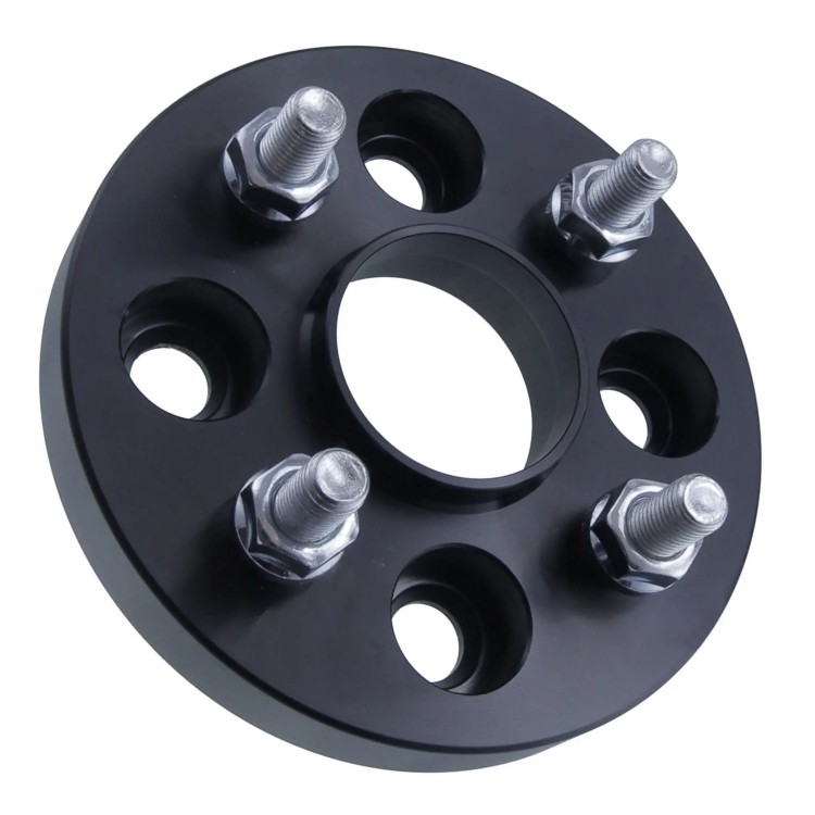
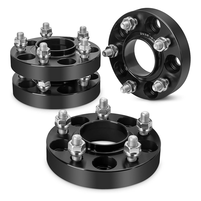
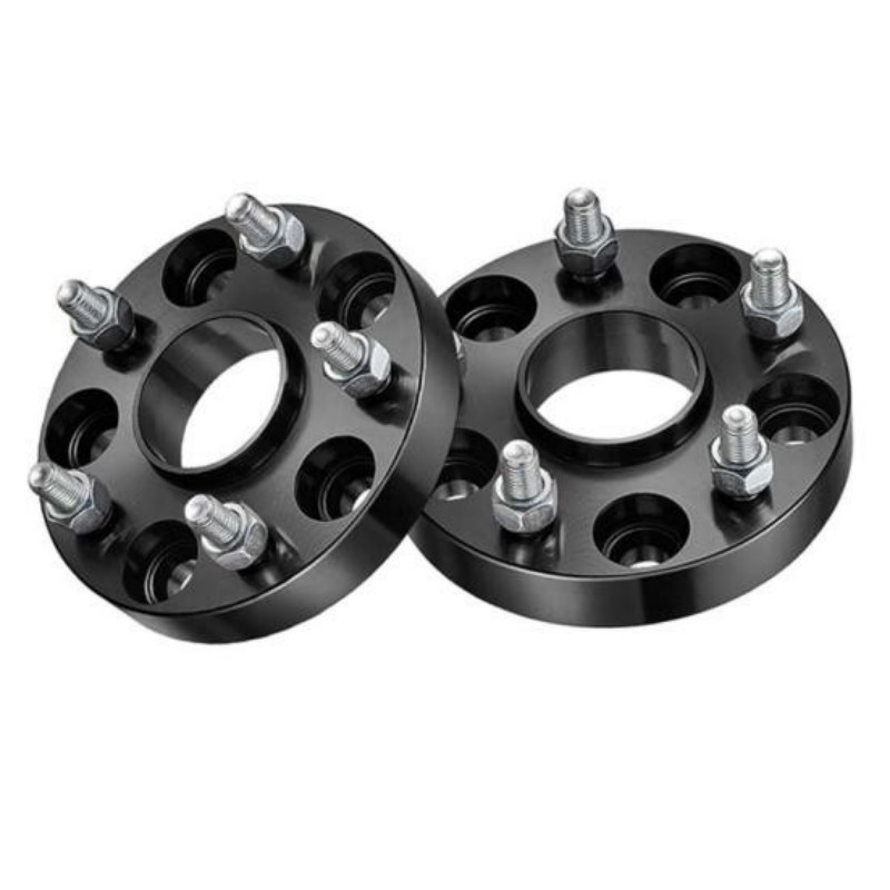
A wheel spacer center bore must fit the vehicle hub on its inboard side. If the spacer has a raised locating lip, that lip must also fit the wheel center bore on the outboard side. PCD, center diameter and profile geometry are separate checks.
One wheel spacer, two centering interfaces
A conventional hub-centric wheel spacer sits between the vehicle hub and the wheel. That position gives the part an inboard interface and an outboard interface. Calling both of them “the center bore” hides the fitment work.
On the vehicle side, the spacer's inner bore passes over and locates on the hub pilot. The inboard mounting face must reach the hub or brake-disc mounting face without rocking. A chamfer or relief around the bore may be needed to clear the radius where the pilot meets that face.
On the wheel side, a raised lip can extend the locating feature toward the wheel. Its outside diameter must suit the wheel center bore or the approved centering arrangement. Its height, top profile and base must also fit inside the wheel's back-pad recess.
“Hub-centric” describes a complete fit, not the presence of a visible lip. A lip with the wrong diameter or profile does not center the wheel. A correct vehicle-side bore does not prove that the wheel side fits.
The bolt pattern belongs to another geometry. PCD defines the number and circle position of the mounting holes. It does not define the diameter in the middle. Use the broader wheel spacer fitment guide when you need to check PCD, thickness and hardware alongside the center bore.
The center-bore number is only the first line of the drawing
CB57.1 or CB60.1 is useful, but a controlled wheel spacer drawing needs enough geometry to answer five separate fit questions.
D1Vehicle hub pilot diameter
The outside diameter of the locating pilot on the vehicle. Measure the actual mating portion, not a dust cap or a larger shoulder behind it.
D2Spacer inner bore and relief
The inboard hole and its base profile must fit over the pilot and clear the hub radius, cap and permitted retention hardware.
D3Spacer wheel-side lip diameter
The lip outside diameter must suit the wheel center bore or the documented ring arrangement used on the outboard side.
L1 / L2Usable pilot and lip heights
Length matters. The features need usable engagement without bottoming before the two mounting faces contact.
C1 / C2Chamfers, radii and lead-ins
Nominal diameters may agree while an edge profile blocks assembly. Specify both the vehicle-side base and wheel-side entry.
F1 / F2Flat contact faces
The hub-to-spacer and spacer-to-wheel faces must contact as intended. Centering does not compensate for a face held apart.
A measurement tolerance also needs context. The drawing should state which surface the dimension applies to, how it is measured, and which mating part it must fit. This article does not publish a universal bore clearance because applications, materials and approval requirements differ.
Read the centering path from hub to wheel
The most useful drawing is a section through the center of the assembly. It shows which cylindrical surfaces locate together and where the flat faces meet.
Start at the vehicle and move outward. Confirm the hub pilot against the spacer bore. Then confirm the spacer lip against the wheel bore. Finally, confirm that both flat interfaces close fully without using the fasteners to pull the parts together.
Eibach's System 6 instructions use this same practical sequence: check the spacer on the hub for correct center and bolt-pattern fit, then perform the check between the wheel and spacer. The instructions say to stop if either check is unsatisfactory. [1]
4×100 does not tell you the center bore
Two wheel spacer products can share the same PCD and use different center bores. J&W currently publishes both examples below. The titles alone demonstrate why “four-lug 4×100” is not a complete specification.
A hub-centric spacer listing with a 57.1 mm center-bore designation.
View the CB57.1 spacerA wheel spacer adapter listing with a 60.1 mm center-bore designation.
View the CB60.1 adapterThe comparison is not a vehicle application chart. It does not mean every component on either product has the same outboard diameter as its inboard bore. It means the center-bore field must travel with the PCD field whenever a wheel spacer is selected, drawn or quoted.
Adapters may need two different center diameters. A part can connect one vehicle-side bore to a different wheel-side bore, just as an adapter may connect two different bolt patterns. The part drawing must label which diameter belongs to which side.
A nominally correct bore can still be the wrong profile
A caliper may show the expected nominal diameter while the wheel spacer stops short of the hub face. That is why a dry fit matters before torque is applied.
| What you observe | Possible interface problem | What to inspect |
|---|---|---|
| Spacer stops before reaching the hub face | Inner bore too small, base chamfer too shallow, pilot shoulder interference, dust-cap interference or protruding retention hardware | Hub pilot diameter and length, bore profile, cap, disc screw, clip and mounting-face relief |
| Spacer reaches the face but rocks | Rust scale, debris, a burr, damaged face or local interference | Cleanliness and condition of the complete annular contact area |
| Wheel stops before reaching the spacer face | Spacer lip too tall, wheel bore too small, wheel lead-in too shallow or wheel pocket interference | Lip diameter and height, wheel center bore, chamfer, back pad and pockets |
| Wheel appears seated but has radial play before tightening | Locating diameters do not create the intended fit, or the assembly is designed around a different centering method | Approved application, actual bore measurements, ring arrangement and fastener-seat geometry |
| New vibration begins after installation | Centering mismatch is possible, but so are face seating, hardware, balance and runout faults | Use the wheel spacer vibration diagnostic order instead of assuming one cause |
If the wheel spacer or wheel will not sit fully against its mating face by the documented assembly method, stop. Extra torque does not remove a geometric obstruction and can hide the gap from view.
H&R's DRS instructions separately check the wheel-side and vehicle-side centering interfaces, including the inner and outer profiles, and require flush seating without play. [2] These are product-specific instructions, so the exact procedure for another system may differ. The general lesson is to inspect both interfaces rather than approving the part by its label.
Specify the physical stack, not a remembered vehicle value
Vehicle databases are useful starting points. They can still miss a different brake package, replacement hub, aftermarket wheel, model-year change or wheel-center ring. Measure the actual parts when the application is uncertain.
- Identify the vehicle side. Record vehicle, year, trim, axle and hub or brake changes. Measure or verify the hub pilot diameter, usable projection and base profile.
- Identify the wheel side. Record wheel manufacturer and part number, center bore, back-pad shape, entry chamfer and available depth for a locating lip.
- State PCD independently. Include the vehicle and wheel bolt patterns even when they are the same. Do not infer center bore from lug count or PCD.
- Add thickness and hardware. Center-bore fit does not approve the spacer thickness, thread, seat type, fastener length or wheel-pocket clearance.
- Request a two-sided drawing. Mark the inboard bore, outboard lip, both chamfers, both contact faces, overall thickness and relevant hardware clearances.
- Dry-fit both interfaces. Follow the exact spacer and vehicle instructions. Check clean, undamaged mating faces and stop if there is rocking, play, bottoming or a visible gap.

Batch control starts with unambiguous dimensions
Parts with similar outside shapes can use different center diameters or profiles. A useful inspection record identifies the part number, drawing revision, measured feature and acceptance requirement.
For a custom wheel spacer, send the mating-part data with the request. A vehicle name and a reference photo do not define the interfaces well enough.
View J&W hub-centric spacer optionsThe wheel spacer measurement guide provides the remaining clearance and hardware fields needed for the complete fitment.
Where hub rings and thin spacers fit into the picture
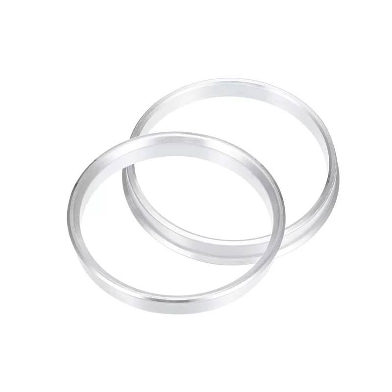
A hub center ring changes a locating diameter
An aftermarket wheel may have a center bore larger than the vehicle's locating feature. An approved hub center ring can adapt that wheel-side bore in the intended arrangement. It does not correct a wheel spacer that cannot seat on the vehicle hub, and it cannot create missing clearance for an incompatible lip or back pad.
Trace the interfaces in order. If a ring is used, state exactly where it sits and which two diameters it connects. Do not assume a loose ring placed somewhere in the stack will make every part hub-centric.
A thin spacer may not reproduce the original pilot
Spacer thickness and pilot projection interact. A plain thin spacer can consume part of the original hub pilot while leaving some pilot available to enter the wheel bore. A thicker hub-centric design may provide a new locating lip. Neither arrangement is automatically correct for every hub and wheel.
The limiting detail may be the original pilot height, the wheel chamfer or the spacer's ability to contain a structurally suitable lip within its thickness. There is no universal thickness at which a lip becomes possible. Use the geometry and the approved product design.
If you are comparing constructions, the slip-on versus bolt-on wheel spacer guide explains the different fastener paths. For a direct centering comparison, use hub-centric versus lug-centric wheel spacers.
Wheel spacer center bore questions
What does CB mean on a wheel spacer?
CB means center bore. On a hub-centric wheel spacer, the vehicle-side bore must fit the vehicle hub pilot. The spacer may also have a wheel-side locating lip that fits the wheel center bore.
Does a wheel spacer center bore need to match exactly?
The wheel spacer must use the specified fit for its approved application. A bore that is too small will not seat, while excessive clearance prevents that bore from locating on the intended pilot. Nominal diameter alone is not enough because chamfers, radii, lip height and mounting faces must also fit.
Can two wheels with the same PCD use different center bores?
Yes. PCD describes the bolt-circle pattern, not the center bore. J&W publishes 4×100 products with CB57.1 and CB60.1, which shows why both dimensions must be specified independently.
Can a hub center ring fix the wrong wheel spacer bore?
A hub center ring may adapt a larger wheel center bore within an approved arrangement, but it does not correct a spacer whose vehicle-side bore, chamfer or mounting face does not fit the hub. Verify every interface separately.
Why will a wheel spacer not sit flush even when the center bore number is correct?
A base chamfer or radius may interfere, the lip may bottom in the wheel, or rust, debris, a retaining clip or a protruding brake-disc fastener may hold the spacer away from the mounting face. Stop the installation and find the obstruction rather than pulling the part flat with the fasteners.