
Wheel spacer fitment file
A spacer can move the wheel spokes away from a caliper. That does not mean it can cure every wheel-to-brake interference. First identify where the contact occurs.
Axial interference between the caliper's outer face and the back of a wheel spoke.
Radial interference between the top of the caliper and the wheel barrel.
The wheel and tire move outward, so fender, liner and outer-body clearance must be remeasured.
A wheel spacer solves a position problem, not every clearance problem
A wheel spacer can create brake caliper clearance when the limiting gap is measured along the axle, most often between the caliper's outboard face and the back of a wheel spoke. The spacer moves the whole wheel outward by its installed thickness.
The same movement does not enlarge the wheel barrel. If the caliper is too tall for the barrel, adding thickness may leave the radial interference unchanged. It can help only if the barrel shape changes far enough along its depth that the shifted wheel places a roomier section over the caliper. That must be checked on the actual wheel or an accurate wheel profile.
Do not choose thickness from wheel diameter, offset or appearance alone. Two wheels with the same nominal diameter, width and offset can have different spoke curvature and inner-barrel profiles.
This distinction is the reason brake manufacturers publish wheel-clearance diagrams for specific calipers or kits. The template maps the full caliper envelope against the inside of the wheel, not just the wheel's catalog size.
Four contact zones lead to four different decisions
Spoke back to caliper face
The gap runs mainly in the axle direction. Moving the wheel outward can add space at this interface.
Spacer may helpInner barrel to caliper bridge
The gap runs mainly in the radial direction. Spacer thickness does not increase wheel diameter.
Check the barrel profileBalance weight to caliper
The weight rotates with the wheel. Its placement and height must remain inside the approved wheel envelope.
Reposition only by an approved methodWheel pad to stock studs
This is a mounting-interface problem on some bolt-on systems, not brake clearance. Wheel pockets and protruding stud length need their own check.
Do not mix the measurementsLook for the smallest gap around the complete rotation of the wheel. A single clear viewing angle is not enough. The caliper body, bridge, bleed screw area and any approved balance-weight position can produce different limiting points.
Axial movement can clear a spoke while radial clearance stays tight
Swipe the diagram to compare the two clearance directions.
Swipe the table to see all columns.
| Observed limit | Measurement direction | What spacer thickness changes | Decision |
|---|---|---|---|
| Caliper face touches spoke back | Mostly axial | Moves the spoke outward by the installed spacer thickness. | Potential solution. Calculate required axial space, then check every other interface. |
| Caliper bridge touches cylindrical barrel | Mostly radial | Does not enlarge the barrel radius. | Usually the wrong solution. A different wheel profile or diameter may be required. |
| Caliper sits near a tapered or stepped barrel | Combined axial and radial | Moves the caliper under a different axial section of the same barrel. | Template required. The result depends on the real contour. |
| Balance weight is the closest item | Location specific | Moves the weight with the wheel but does not reduce its height. | Review wheel balancing. Follow the wheel and brake provider's approved placement. |
Measure with the brake kit's profile, not a guessed caliper width
A caliper is not a rectangular block. Its bridge, body, fittings and outer face occupy different parts of the wheel cavity. A manufacturer profile captures that shape and locates it from the wheel mounting surface and hub center.
-
Identify the exact brake configurationRecord the axle, caliper or brake-kit part number, rotor configuration and any bracket or hat that affects caliper position.
-
Obtain the matching clearance profileUse the drawing supplied for that configuration. A template for a similar caliper is not proof of fit.
-
Print without scalingFollow the drawing instructions and verify its printed reference dimensions with a ruler before cutting it out.
-
Locate it from the wheel center and mounting padPlace the profile inside the wheel exactly as the brake manufacturer directs. Rotate it through the wheel and inspect spokes, barrel and balance weights.
-
Record the limiting zone and the actual gapWrite down where the minimum occurs. Do not reduce the result to a single clearance number without its location.
One AP Racing installation profile specifies 4.00 mm minimum wheel clearance, while a Wilwood wheel-clearance template specifies .080 inch for its referenced kit. Those figures belong to those exact documents. Use the value required by the brake, wheel and vehicle providers for the setup being checked.
Build an inner-clearance gain and an outer-clearance loss budget
For a simple spoke-to-caliper axial gap, the wheel moves outward by the spacer's installed thickness. That gives a useful first calculation, but it is not approval to install the part.
candidate thickness ≥ required final gap − current measured gap
Use this only when both gaps are measured in the same axial direction at the same limiting point.
If the wheel already interferes, record the overlap as a negative current gap. The required final gap must come from the applicable brake, wheel or vehicle documentation.The same candidate thickness also moves the wheel and tire outward. At comparable points, inner space increases while outer space decreases by roughly the same installed amount. Check the tire shoulder and sidewall against the fender, liner and body through steering travel and suspension movement. The wheel spacer measurement guide covers that full clearance path.
A large theoretical gap at the caliper is not a better result if the tire then contacts the body. Choose the smallest configuration that satisfies the documented brake clearance and all wheel, tire and hardware requirements.
PCD, center bore, seating and hardware still have to work together
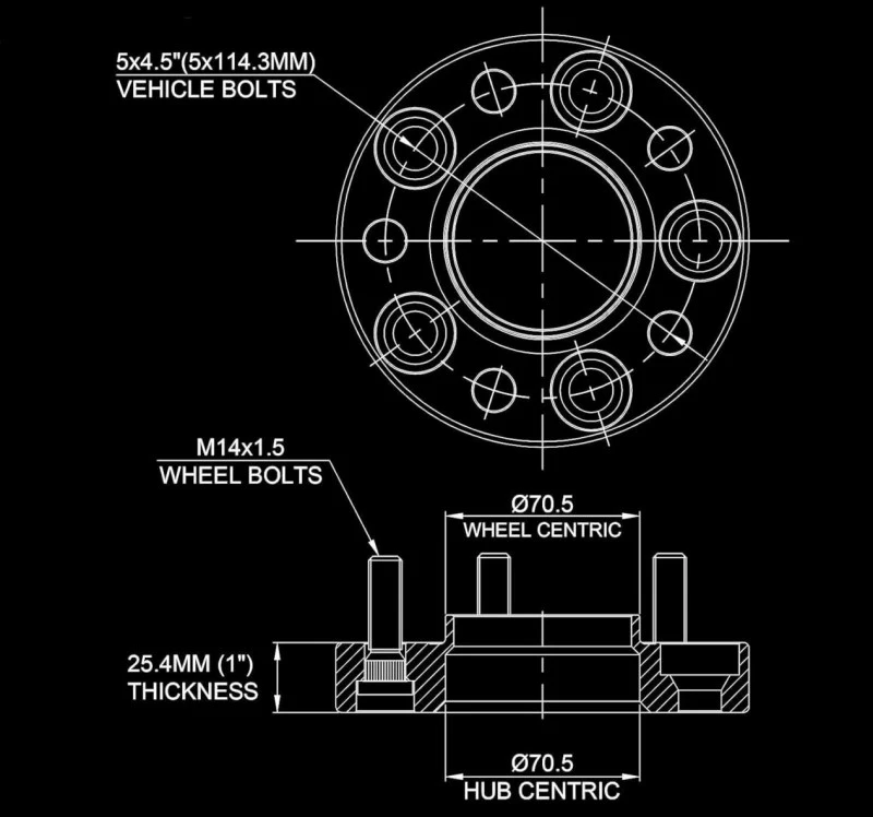
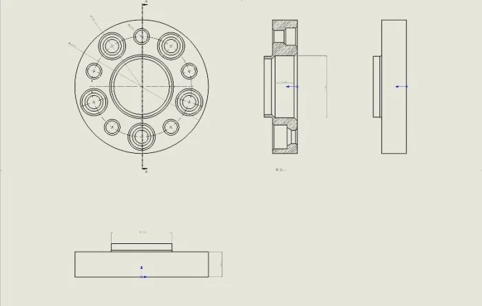
Brake clearance cannot compensate for a spacer that does not match the hub and wheel. Confirm bolt pattern, hub-side and wheel-side center diameters, the available hub lip, mounting-face contact, fastener seat, thread specification and usable engagement under the instructions for the exact assembly.
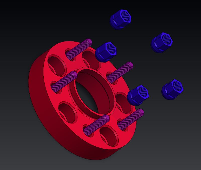
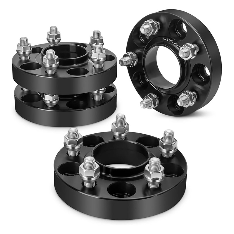
A thin slip-on spacer and a bolt-on adapter use different fastening arrangements. The slip-on versus bolt-on guide explains the interface differences. If the wheel uses bolts, confirm the replacement bolt's thread and seat as well as usable thread engagement. If it uses studs, verify stud and nut compatibility plus any stock-stud protrusion behind the wheel.
Stop for barrel contact
If the caliper is radially too tall for a cylindrical barrel, extra spacer thickness is not a substitute for a compatible wheel.
Stop for uncertain seating
If the spacer rocks, bottoms on a radius or prevents full face contact, do not use torque to pull the parts together.
Stop for missing instructions
If torque, hardware, inspection or clearance requirements are unknown, obtain the exact product and vehicle instructions before installation.
A useful clearance request names the limiting point
“I need a spacer for big brakes” is not enough to select a safe fitment. Record the assembly in a form that another person can verify.
Photos should show the wheel mounting pad, hub, spacer profile and the limiting brake area. A straight-on photo without a scale may locate the problem, but it cannot establish the gap by itself.
Use the next guide that answers the remaining fitment question
Send the caliper profile and the limiting gap
Include the vehicle and axle, wheel specification, brake configuration, contact-zone photo, measured gap, required clearance and remaining outer space. Those details make the spacer discussion specific.
Safety note: This page explains a measurement method, not a vehicle-specific installation approval. Follow the vehicle, brake, wheel, spacer and hardware instructions. Have unresolved fitment, steering, braking or clearance questions inspected by a qualified automotive professional.