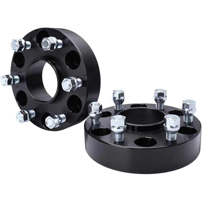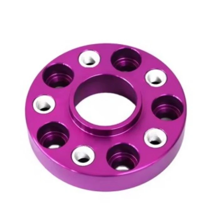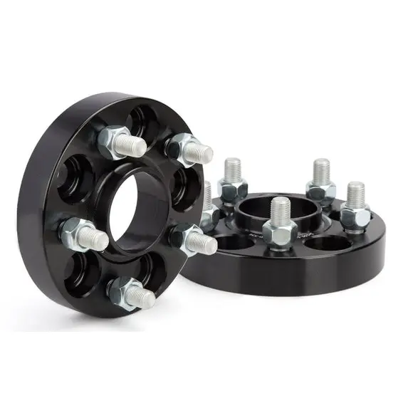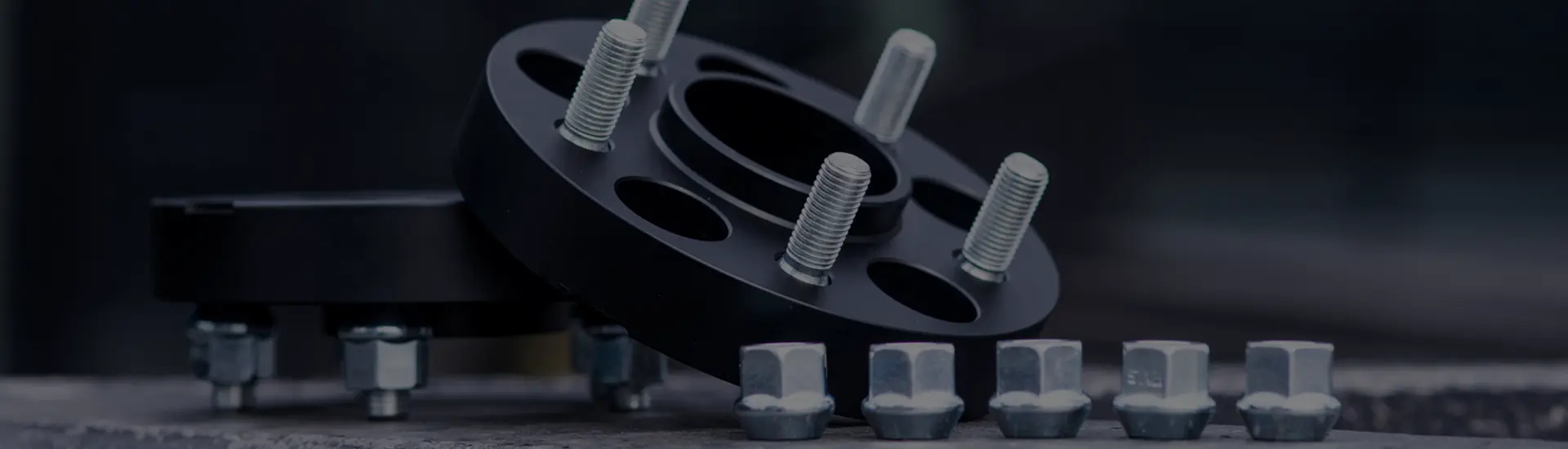

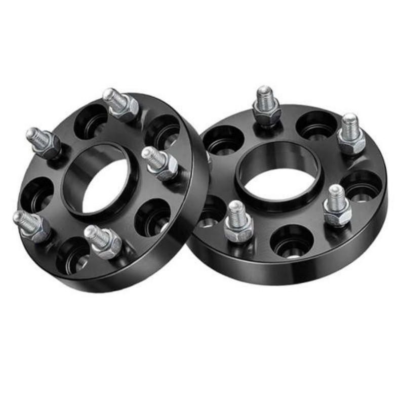
The correct wheel spacer matches five things: bolt pattern (PCD), vehicle hub diameter, wheel center bore, the thickness needed after measuring clearance, and hardware geometry. Check them in that order. A spacer that matches only “5-lug” or only the vehicle model is not enough to confirm fitment.
Wheel-spacer searches often begin with a vehicle name and a thickness: “20 mm for a BMW,” “1.5 inch for a Jeep,” or “5x114.3 spacer.” Those descriptions leave out the interfaces that decide whether the assembly can sit flat, center correctly and fasten with the specified hardware.
This guide gives vehicle owners, workshops and wholesale buyers one repeatable way to specify a spacer. It complements our separate explanations of hub-centric and lug-centric spacers and wheel-spacer design and installation safety.
The five checks, in the right order
Do not reverse this sequence. Choosing thickness first can lead to a product that looks correct but cannot locate on the hub, clear the original studs or use the correct fastener engagement.
First decide whether you need a spacer or an adapter
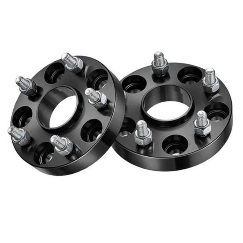
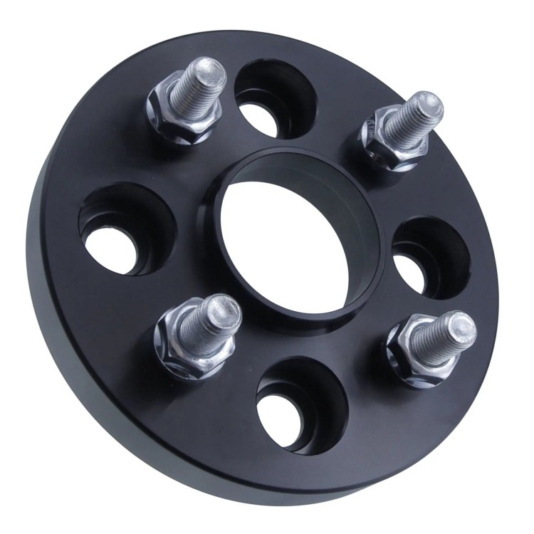
A wheel spacer primarily moves the wheel outward and normally keeps the same PCD on both sides. A wheel adapter can move the wheel outward and convert from one PCD to another—for example, from a vehicle-side pattern to a different wheel-side pattern.
Product names are not perfectly consistent across markets. Some bolt-on spacers are sold as “spacer adapters” even when both PCDs are identical. Confirm the drawing: vehicle-side PCD and center bore, wheel-side PCD and center bore, thickness, and thread specification.
| System | What it changes | Typical hardware question | Critical clearance check |
|---|---|---|---|
| Slip-on spacer | Wheel position; same PCD | Are longer bolts or studs specified? | Enough hub-lip engagement and inner/outer clearance |
| Bolt-on spacer | Wheel position; usually same PCD | How does the spacer attach, and how does the wheel attach? | Original stud or bolt-end clearance behind the wheel |
| PCD adapter | Wheel position and bolt pattern | Two interfaces and possibly two thread specifications | Adapter thickness, fastener heads and wheel back-pad pockets |
Eibach’s official product guide makes the same practical distinction between slip-on systems that require extended hardware and bolt-on systems with their own studs or threads. It also warns that some bolt-on applications need pockets in the rear wheel pad to clear the original hardware. See the Eibach PRO-SPACER system descriptions.


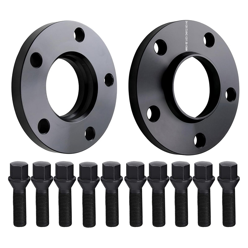
PCD: match both the hole count and circle diameter
PCD means Pitch Circle Diameter: the diameter of the circle running through the centers of the fixing holes. Wheel maker OZ Racing defines it together with the number of holes, which is why a pattern is written as 5x112, 5x114.3 or 6x139.7. The first number is the hole count; the second is the circle diameter in millimeters. The definitions are shown in the OZ Racing wheel measurement guide.
A spacer must sit over every stud or align with every threaded hole without force. “Five-lug” is not a fitment specification because multiple five-hole PCDs exist. Likewise, 5x114.3 and 5x115 are not interchangeable simply because the numbers are close.
Do not force a spacer onto the hub, enlarge holes or use tightening force to pull a misaligned part into place. Eibach’s installation instructions require confirming the bolt pattern and hub center before continuing.
Center bore: specify the hub side and the wheel side
The center bore is the diameter of the central opening where the wheel or spacer locates on the vehicle hub. For a hub-centric spacer, there are two relevant dimensions:
- Spacer inner bore: must match the vehicle hub diameter and clear any hub chamfer or radius.
- Spacer outer lip: must match the wheel center bore or the approved centering arrangement used by that wheel.
The part must sit flush against the hub mounting face. A nominally correct diameter can still fail if the spacer’s chamfer, lip height or relief conflicts with the hub, brake-disc retaining hardware or wheel back pad. That is why a supplier should work from a dimensioned drawing or a verified vehicle-and-wheel application, not just a center-bore number.
If an aftermarket wheel has a larger center bore than the vehicle hub, a separate hub center ring may be part of the approved fitment. Do not assume that a ring can correct a spacer whose own vehicle-side bore is wrong.
How spacer thickness changes effective wheel offset
Wheel offset, also called ET, is the distance between the wheel centerline and its hub-mounting surface. Adding a spacer moves that mounting position outward. For a basic same-wheel comparison:
effective offset ≈ marked wheel offset − spacer thickness Use millimeters for both values.
Example: a wheel marked ET45 used with a 15 mm spacer sits approximately like an ET30 wheel, assuming the wheel itself is unchanged. The wheel and tire move outward by roughly the spacer thickness.
This calculation describes position; it does not confirm clearance. Wheel width, tire section width, tire shape, suspension movement, steering angle, brake package and fender geometry still matter. Moving the wheel outward also changes the assembly’s relationship to steering and suspension components, so use an application approved for the vehicle rather than treating the formula as permission to select any thickness.
Choose thickness from measured clearance, not appearance
Measure both sides of the problem. The outer measurement checks how far the wheel can move toward the fender. The inner inspection confirms that the new position solves the intended brake, suspension or tire clearance issue without introducing another contact point.
- Record the current setup. Note wheel size and offset, tire size, suspension changes, brake package and current clearances.
- Measure the outer gap. Place a straightedge at the closest fender point and measure horizontally to the tire or wheel’s outermost point.
- Keep a margin. Eibach recommends selecting a spacer slightly thinner than the measured flush-to-fender distance to reduce the risk of tire contact.
- Check the inside. Inspect the caliper, upright, control arms, liners, hoses and sensor wiring through full steering movement.
- Validate dynamic clearance. Suspension compression, tire deflection, steering lock and vehicle loading can reduce a gap that appears adequate while parked.
A ruler measurement at static ride height is a starting point, not the final approval. A trained installer should verify the complete wheel-and-tire package on the vehicle.
Hardware fitment: thread, seat, length and clearance
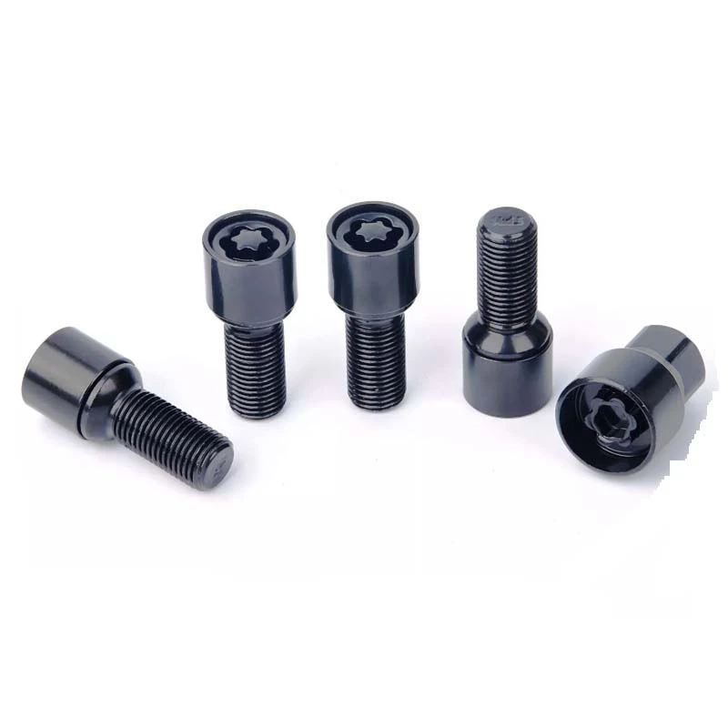
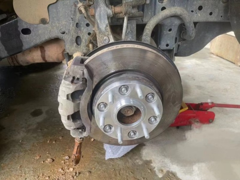
Hardware is part of the fitment specification. Confirm the thread diameter and pitch, fastener seat shape, usable length, wrench clearance and the wheel’s back-pad geometry. For press-in studs, the knurl diameter and knurl length also need to match the intended hub.
Slip-on spacers
A slip-on spacer normally needs longer wheel bolts or studs. H&R’s application notes state that replacement bolts for its DR systems must be longer than the originals by the spacer width, while retaining the correct bolt-head shape. That is a useful specification rule, but the final part must still follow the exact application instructions. See the H&R TRAK+ application note.
Bolt-on spacers and adapters
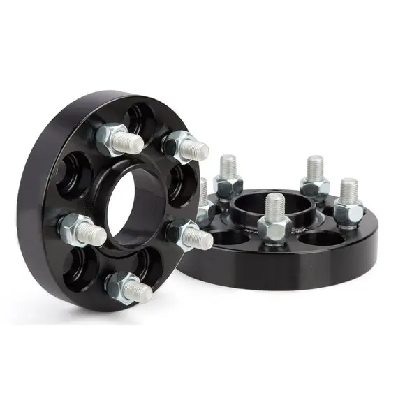
With a bolt-on design, the spacer first attaches to the hub and the wheel then attaches to the spacer. If the original studs project beyond the spacer face, the wheel needs sufficient back-pad pockets—or the approved application must specify another solution. The wheel must sit fully flat on the spacer. Never accept a visible gap between mounting faces.
Thread engagement and torque
There is no responsible universal answer such as “six turns fits every vehicle.” Required engagement varies by thread diameter and pitch, and the vehicle manufacturer’s instructions take priority. Eibach and H&R publish different minimum-turn values for different threads in their system documentation. Use the value for the exact product and application.
Clean mating faces, hand-start all fasteners, tighten in the specified crossing sequence and finish with a calibrated torque wrench. Use the torque in the vehicle workshop manual or the wheel/spacer manufacturer’s approved application instructions. Eibach’s System 6 installation instructions also require free-rotation and clearance checks before road testing. Recheck torque at the interval specified for the installed system.
Stacking two or more spacer rings is explicitly prohibited in Eibach’s installation instructions. If more thickness is required, specify one correctly engineered part for the intended application.
A fitment worksheet buyers can send to a supplier
Complete one line for each vehicle-and-wheel combination. If any field is unknown, mark it as unknown rather than copying a value from a similar model.
| Field | Vehicle side | Wheel side | Why it matters |
|---|---|---|---|
| PCD | Hub pattern | Wheel pattern | Confirms spacer or adapter drilling |
| Center diameter | Hub outside diameter | Wheel center bore | Defines inner bore and outer lip |
| Fastener | Stud/bolt thread, seat and original length | Wheel seat geometry and pocket depth | Defines compatible hardware and clearance |
| Position | Available inner and outer clearance | Wheel width, offset and tire size | Defines a defensible thickness range |
| Application | Make, model, year, trim and axle | OE or aftermarket wheel part number | Separates look-alike vehicle packages |
Published J&W stock examples
The following examples are currently published on the J&W wheel spacer category page. They are useful starting points for wholesale discussions, not universal fitment approval for every model year, trim, axle, brake or wheel package.
| Vehicle platform | PCD | Center bore | Thread pitch | Published stock thickness |
|---|---|---|---|---|
| Ford Mustang | 5x114.3 | 70.5 mm | M14x1.5 | 20 / 25 / 30 mm |
| Ford Ranger / Bronco | 6x139.7 | 93.1 mm | M12x1.5 | 30 / 35 / 50 mm |
| Ford F-150 / Raptor | 6x135 | 87.1 mm | M14x1.5 | 25 / 38 / 50 mm |
| Jeep Wrangler JL | 5x127 (5x5) | 71.5 mm | M14x1.5 | 32 / 38 / 50 mm |
| Toyota Tacoma / Hilux | 6x139.7 | 106 mm | M12x1.5 | 25 / 30 / 38 mm |
Source: current J&W Auto Parts wheel spacer category page, checked 20 Aug 2026. Confirm the exact vehicle and wheel package before ordering or installation.
Pre-installation and final verification
A part number is not the end of fitment. Before installation, compare the delivered spacer with the approved drawing and inspect the mounting faces, bores, lip, threads, studs and finish for damage. Then use this sequence:
- Confirm the vehicle is safely supported and the installer has the correct service information.
- Clean rust, dirt and obstructions from the hub and wheel mounting faces.
- Dry-fit the spacer on the hub. It should sit flush, align freely and have no unintended interference.
- Dry-fit the wheel on the spacer. Check center-lip engagement, back-pad pockets and fastener-seat contact.
- Install with the specified hardware and torque procedure.
- Rotate the wheel by hand and check brake, ABS component, suspension and body clearance.
- Verify steering movement and dynamic clearance before normal use; recheck fasteners at the specified interval.
The OZ Racing mounting and maintenance manual likewise calls for clean contact surfaces, hand-starting fasteners, a crossing sequence, manufacturer-specified torque, free wheel rotation and a subsequent tightness check. If instructions for the vehicle, wheel and spacer differ, stop and resolve the conflict with the manufacturers or a qualified installer.
What a B2B buyer should include in an RFQ
A useful quotation request lets the supplier confirm fitment and quote the same product you intend to approve. “Black 20 mm spacer for Ford” is not enough.

Copy this wheel-spacer RFQ checklist
- Vehicle make, model, year, trim, market and front/rear axle
- Vehicle-side PCD and measured hub diameter
- Wheel-side PCD, center bore, width, offset and part number
- Required spacer thickness and the clearance measurement behind that choice
- Slip-on, bolt-on or PCD-converting adapter
- Stud or bolt thread diameter, pitch, seat type and usable length
- Original stud projection and wheel back-pad pocket depth, where relevant
- Material, finish, branding, packaging and order quantity
- Drawing format, inspection report and compliance documentation required for your market
- One physical sample or fitment validation stage before mass production
J&W currently lists forged 6061-T6 and 7075-T6 aluminum options, CNC manufacturing and custom PCD, center-bore, thickness and finish services on its wheel spacer supplier page. These are company-published offering details; the approved purchase drawing and order documents should define the exact specification for each project.
Six fitment mistakes that create avoidable returns
- Ordering by vehicle model alone. Model year, trim, axle, brake and wheel packages can differ.
- Treating “five-lug” as a PCD. Hole count does not supply the pitch-circle diameter.
- Checking only the vehicle-side center bore. A hub-centric part also needs the correct wheel-side lip.
- Choosing a flush look with no dynamic margin. Static fender clearance can disappear in steering or compression.
- Ignoring seat geometry. Correct thread size does not make a conical, ball or flat seat interchangeable.
- Assuming all original hardware can be reused. Slip-on and bolt-on systems have different length and clearance requirements.
Wheel spacer fitment FAQ
How do I know what size wheel spacer I need?
Confirm the vehicle and wheel PCD, both center-bore interfaces, wheel offset, available inner and outer clearance, spacer type, and compatible hardware. Measure the outer gap with a straightedge, choose a thickness below the available clearance, and verify full rotation and suspension clearance before road use.
Does a wheel spacer change wheel offset?
It changes the wheel's effective position. As a fitment calculation, effective offset is approximately the wheel's marked offset minus spacer thickness. A +45 mm wheel used with a 15 mm spacer therefore sits like an approximately +30 mm setup, assuming the same wheel.
Are PCD and center bore the same measurement?
No. PCD describes the diameter of the circle through the fastener holes and is written with the hole count, such as 5x112. Center bore is the diameter of the central opening that locates on the hub.
Can I use the original wheel bolts with a slip-on spacer?
Usually not unless the approved application instructions explicitly allow it. A slip-on spacer normally requires longer bolts or studs while preserving the correct thread, seat geometry and required engagement. Follow the vehicle, wheel and spacer manufacturer's instructions.
What is the difference between a wheel spacer and a wheel adapter?
A spacer primarily moves the wheel outward while retaining the same bolt pattern. An adapter can also convert between two bolt patterns, so it has a vehicle-side pattern and a wheel-side pattern. Product naming varies, so the drawing matters more than the label.
What information should a buyer send for a wheel spacer quotation?
Send the vehicle make, model, year and trim; vehicle-side PCD and hub diameter; wheel-side PCD and center bore; desired thickness; stud or bolt thread and seat type; wheel offset and back-pad pocket depth; quantity; finish; packaging; and any drawing, inspection or compliance requirements.
Technical sources
- OZ Racing — Technology: The Wheel. Definitions of offset, PCD, hole count and center bore.
- Eibach — PRO-SPACER Wheel Spacers. Spacer system types and clearance measurement method.
- Eibach — Pro-Spacer System 6 Installation Instructions. Fitment, hardware, torque-wrench and post-installation checks.
- H&R — TRAK+ Application Note. Extended bolt length, seat type and thread-specific engagement guidance.
- OZ Racing — Mounting and Maintenance Manual. Contact-surface, tightening, free-rotation and recheck guidance.
Need a spacer drawing checked before you order?
Send J&W Auto Parts the vehicle-side and wheel-side dimensions, target thickness, hardware details and order quantity. We can review the requested specification for a standard wheel spacer or a PCD-converting wheel adapter.
Send Your Fitment RequirementsEditorial scope: This guide explains specification and fitment checks; it is not a substitute for the vehicle workshop manual, wheel instructions, product-specific installation instructions or local road regulations. Product examples and J&W offering details were checked against the live J&W Auto Parts website on 20 Aug 2026.