
Start with the complete wheel-to-hub stack
What Is a Wheel Spacer?
A wheel spacer moves a wheel outward from the vehicle hub. The useful question is not whether the part creates more stance, but whether its thickness, interfaces and hardware solve a measured fitment need.

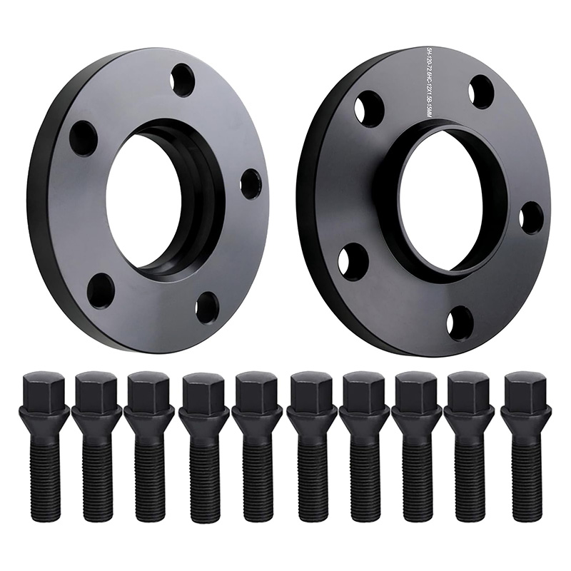
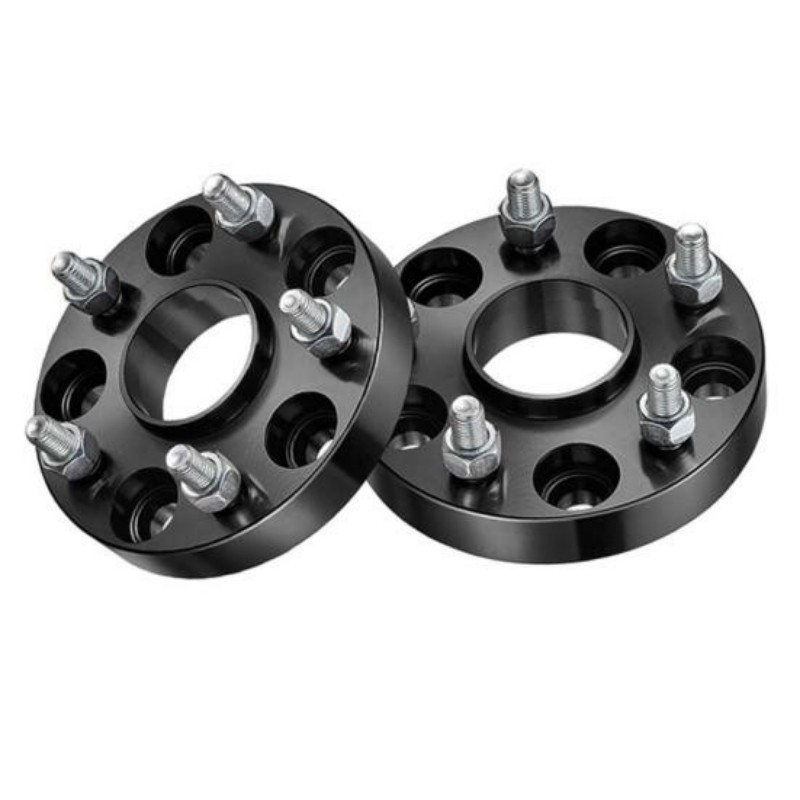
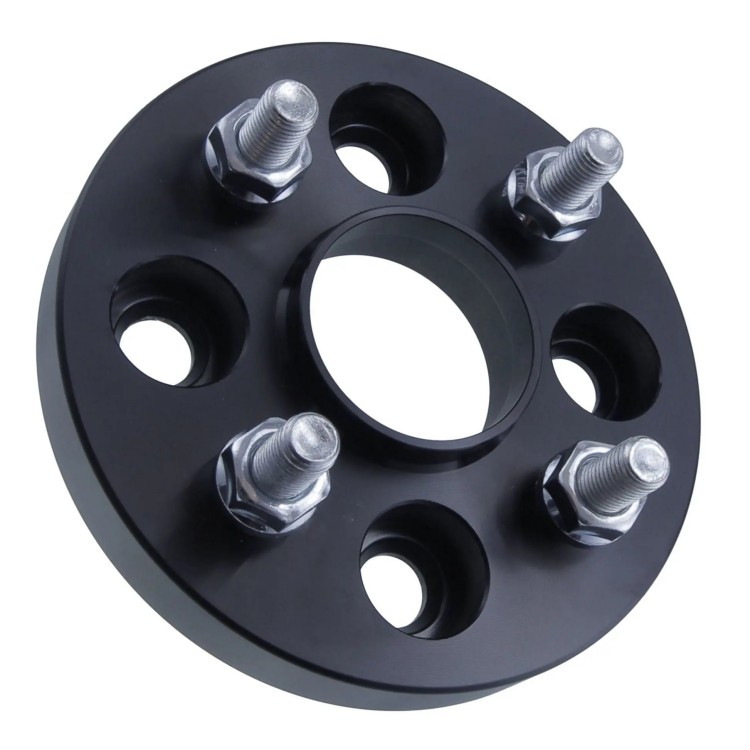
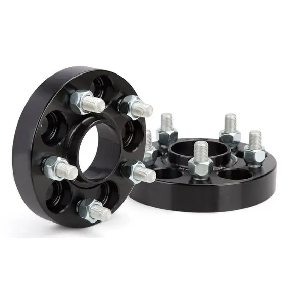
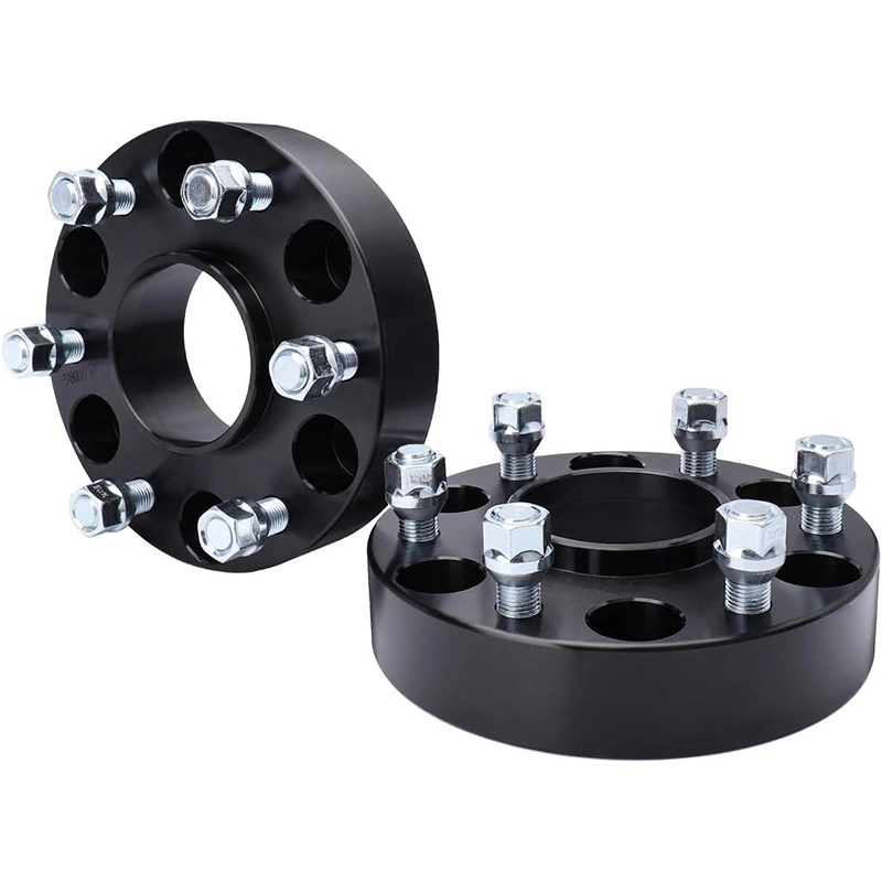
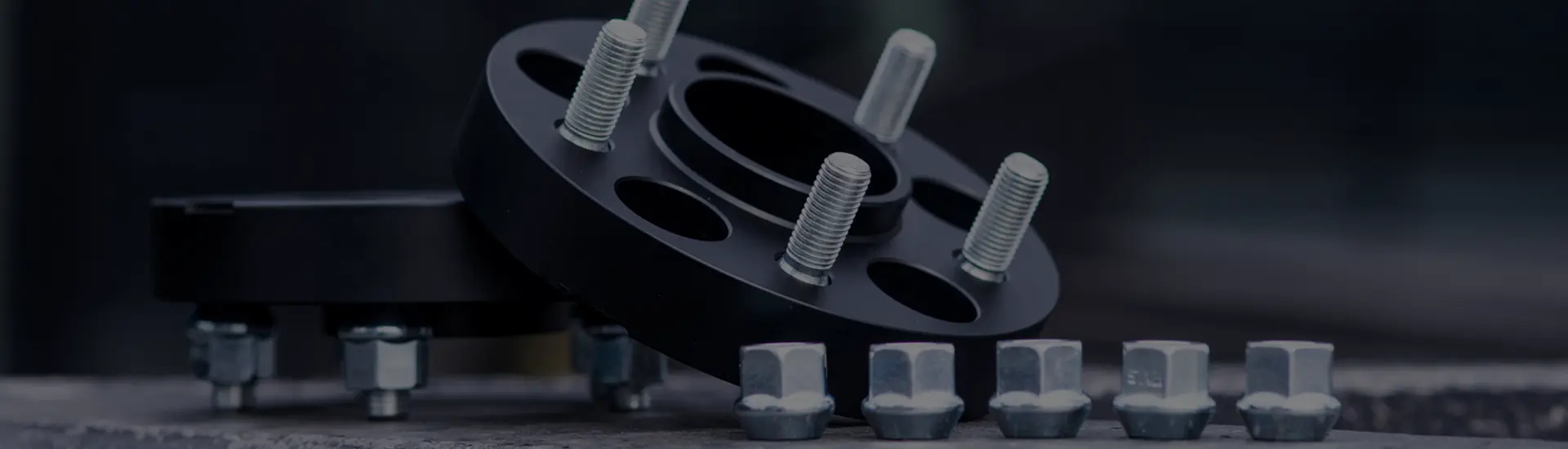
A wheel spacer is a component installed between a vehicle hub and wheel. Its thickness moves the wheel outward. Depending on the design, the wheel may continue to use longer original-style fasteners, or the spacer may attach to the hub and provide a second set of studs or threads for the wheel.
What a wheel spacer changes, and what it leaves alone
Wheel spacers are used when a wheel needs to sit farther away from the hub. The reason may be inner clearance at a brake caliper or suspension component, a required wheel position after changing wheels, or an intended change in stance. The spacer only creates an outward shift. It does not decide whether that final position is suitable.
It changes
- the wheel's outward position;
- effective wheel offset;
- inner and outer clearance;
- track width when used on both sides of an axle;
- the wheel centerline's relationship to the bearing and, on a steering axle, the steering axis.
It does not automatically change
- wheel width or diameter;
- the wheel's own marked offset;
- the hub or wheel bolt pattern, unless the part is an adapter;
- a wheel center bore that does not match the required locating interface;
- toe, camber or caster simply because a flat spacer was added.
A spacer also cannot repair a bent wheel, damaged hub, worn bearing or poor wheel balance. If the original problem is vibration or looseness, identify that problem before adding another interface.
The spacer becomes part of the wheel-to-hub stack
Fitment depends on two sides of the part. The inboard face meets the vehicle hub. The outboard face meets the wheel. Each side has its own center location, contact surface and fastener path.
For a hub-centric design, compare the vehicle hub pilot with the spacer's inboard bore and profile. Then compare the spacer's outboard locating feature with the wheel center bore and back-pad shape. A nominal diameter may match while a chamfer, radius or pilot height still prevents full seating.
Slip-on spacer, bolt-on spacer and PCD adapter are different parts
Product names are often used loosely. The attachment and hardware path tell you more than the color or outside shape.
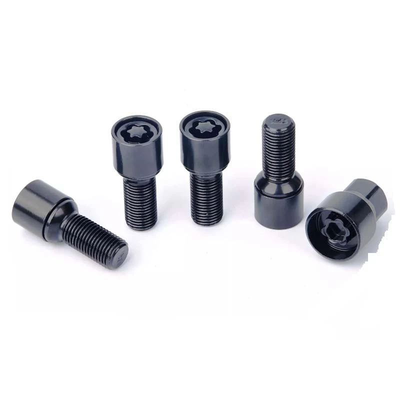
The spacer slides over the hub or existing studs. The wheel still fastens to the vehicle's studs or threaded hub, so usable fastener length must account for the spacer thickness. Extended studs or bolts may be required for the specific system.
The spacer first attaches to the hub. The wheel then attaches to studs or threads on the spacer. Original stud projection and recesses in the wheel back pad must be checked so the wheel can sit flat.
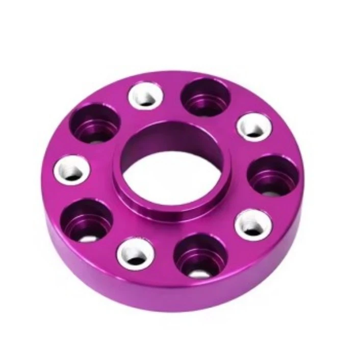
An adapter changes an interface, commonly from one PCD to another. It requires both the vehicle-side and wheel-side patterns, center dimensions, hardware and thickness to be defined separately.
The slip-on versus bolt-on guide compares the attachment systems without treating one type as universally better.
Thickness changes effective offset, track width and clearance together
A spacer shifts the complete wheel outward by its thickness when it seats flat between the hub and wheel. That single change affects several dimensions at once.
ETeffective = ETwheel - sIf a wheel is ET45 and the spacer is 15 mm, the simplified effective position is ET30. The wheel's cast or stamped marking remains ET45; the installed position changes.
Swipe the table to see all columns.
| Result | Approximate change with spacer thickness s | What still needs checking |
|---|---|---|
| Inner wheel clearance | Increases by about s at comparable points. | Brake caliper shape, suspension movement and the actual nearest contact point. |
| Outer wheel position | Moves outward by about s. | Fender, liner and body clearance at steering lock and suspension compression. |
| Track width | Increases by about 2s when equal spacers are fitted on both sides of one axle. | The vehicle's definition of track and any local modification limits. |
| Effective offset | Positive offset decreases by s. | Wheel width, original offset and final wheel centerline. |
| Bearing lever arm | The wheel centerline moves farther from the hub bearing. | Vehicle load, wheel and tire package, use case and bearing design. |
| Front scrub radius | The tire contact patch shifts outward relative to the steering axis. | Original signed scrub radius, tire geometry, ride height and suspension layout. |
The effects belong in one calculation, but they answer different questions. Effective offset describes installed wheel position. Bearing leverage describes load geometry. Scrub radius concerns the tire contact patch and steering axis. Do not use the offset equation as proof that the bearing or steering result is acceptable.
The correct size begins with the limiting clearance
There is no single wheel spacer thickness that fits every vehicle using the same bolt pattern. Start at the exact point where clearance is limited. Measure the gap and the amount of additional clearance required, then include a margin appropriate to movement, deflection and the vehicle's use.
A brake-caliper problem and a fender-position goal use different reference points. Measuring from the tire to the fender does not prove spoke-to-caliper clearance. Measuring at one steering position does not prove clearance through full lock and suspension travel.
Use the linked wheel spacer measurement guide for a worksheet covering front and rear data, hub dimensions, wheel dimensions, hardware and target thickness.


Start with the problem, then measure the dimension it depends on
"I need a 15 mm wheel spacer" names a thickness, not a complete part. The same 15 mm shift may solve an inner-clearance problem, create an outer-clearance problem, or be unrelated to the fault being diagnosed. Define the contact point or target position first.
Swipe the table to see all columns.
| Problem or goal | Measure this first | What a spacer can change | What the measurement does not prove |
|---|---|---|---|
| Wheel spoke touches a brake caliper | The smallest gap or interference at the exact spoke-to-caliper location. | Moves the wheel mounting pad and spoke profile outward by the selected thickness. | Clearance at every spoke contour, with another wheel design, or under all operating conditions. |
| Inner tire or rim is too close to suspension | The nearest inner-sidewall or rim gap through the steering positions and suspension states that can be checked safely. | Moves the complete wheel-and-tire assembly outward. | Outer fender and liner clearance after the shift. |
| A more outward wheel position is wanted | The current outermost tire or wheel position relative to the body, checked by axle. | Changes installed position in direct relation to spacer thickness. | Clearance during compression, steering lock, tire growth or body movement. |
| The wheel and hub have different bolt patterns | Both PCDs, both center interfaces, both hardware paths and the required thickness. | A purpose-designed adapter can provide separate vehicle-side and wheel-side patterns. | That any ordinary spacer, redrilling or a matching hole count will make the combination suitable. |
| Vibration appeared after installation | Mounting-face seating, centering, hardware, runout and wheel-and-tire condition. | A correctly specified replacement may remove an interface error. | That spacer thickness caused the vibration or that a thicker part will cure it. |
This separation matters because one measurement cannot approve the whole assembly. A fender gap answers an outer-position question. It says nothing about PCD, center-bore fit or usable fastener engagement.
Collect the dimensions before choosing a product
A complete specification joins three records: the vehicle-side interface, the wheel-side interface and the required installed position. Leave any one of them undefined and a matching product title can still hide a mismatch.
- Vehicle and axleRecord year, model, trim and whether the fitment is front, rear or both.
- Hub PCD and pilotMeasure the bolt pattern, hub pilot diameter, pilot height and the profile around the mounting face.
- Wheel specificationRecord wheel width, diameter, marked offset, center bore and back-pad recesses.
- Fastener systemIdentify bolt or stud thread, seat type, original projection and usable engagement.
- Limiting clearancePhotograph and measure the nearest brake, suspension, fender or body contact point.
- Final targetState the minimum thickness needed, expected vehicle use and whether other wheel or tire changes are planned.
The wheel spacer fitment guide brings these items into one approval sequence. The product category can then be used to compare the available wheel spacer range.
A wheel spacer is the wrong fix when the base assembly is unresolved
Stop before installation if:
- the spacer cannot sit flat against the hub;
- the wheel cannot sit flat against the spacer;
- PCD, center interfaces or fastener specifications are uncertain;
- the available hardware path does not provide verified engagement and seating;
- the hub, wheel, studs, bolts or bearing show damage or looseness;
- the final wheel position causes contact through steering or suspension motion;
- the vehicle or local rules do not permit the proposed configuration.
Hub-centric location does not compensate for a wrong bolt pattern, unsuitable thickness or damaged mounting face. A precise part can still be the wrong part for the stack.
Before installation, use the wheel spacer fitment guide to review PCD, center bore, offset, thickness and hardware as one approval sequence. Vehicle-specific installation instructions and hardware specifications still take priority.
Use the guide that matches the decision in front of you
Describe the fitment problem before naming the spacer
Send the vehicle and axle, wheel specification, hub dimensions, measured clearance, required thickness and hardware details. J&W can discuss a standard or custom configuration from the complete interface data.
- OZ Racing: The wheel, used for the definitions of wheel offset, PCD and center bore.
- Eibach: PRO-SPACER, used to cross-check slip-on and bolt-on system distinctions and outward wheel positioning.
Safety note: This is a general fitment guide. Vehicle-specific instructions, hardware specifications and applicable regulations take priority. Have the final assembly inspected by a qualified automotive professional when suitability is uncertain.