
Front suspension geometry
Do Wheel Spacers Affect Scrub Radius?
A spacer moves the tire contact patch relative to the steering axis. The original scrub-radius sign determines whether that move approaches zero or creates more positive scrub.
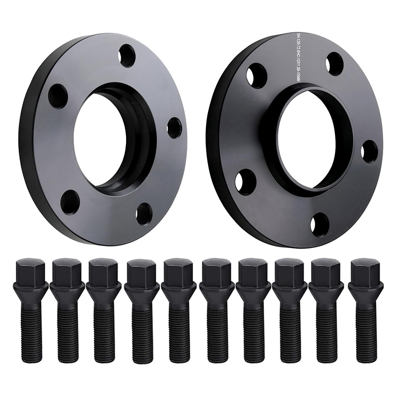

Yes, a front wheel spacer changes scrub radius in a static front-view model. It moves the wheel and tire outward while the suspension's steering-axis hard points stay in place. The signed scrub radius therefore shifts outward by approximately the spacer thickness when the wheel, tire, ride height and alignment geometry remain otherwise unchanged.
Scrub radius is the gap between two ground points
View a front suspension from ahead of the vehicle. Extend the steering axis downward until it meets the road. Then mark the center of the tire contact patch. The horizontal distance between those two points is the static scrub radius.
The sign convention matters. Some drawings reverse the labels, so a number without a diagram or stated convention can be misleading. The mechanical point is the relative location of the two ground points.
Scrub radius is not wheel offset, steering-axis inclination or track width. Those dimensions influence the geometry, but they are not interchangeable names.
A spacer shifts the contact patch outward, not the steering axis
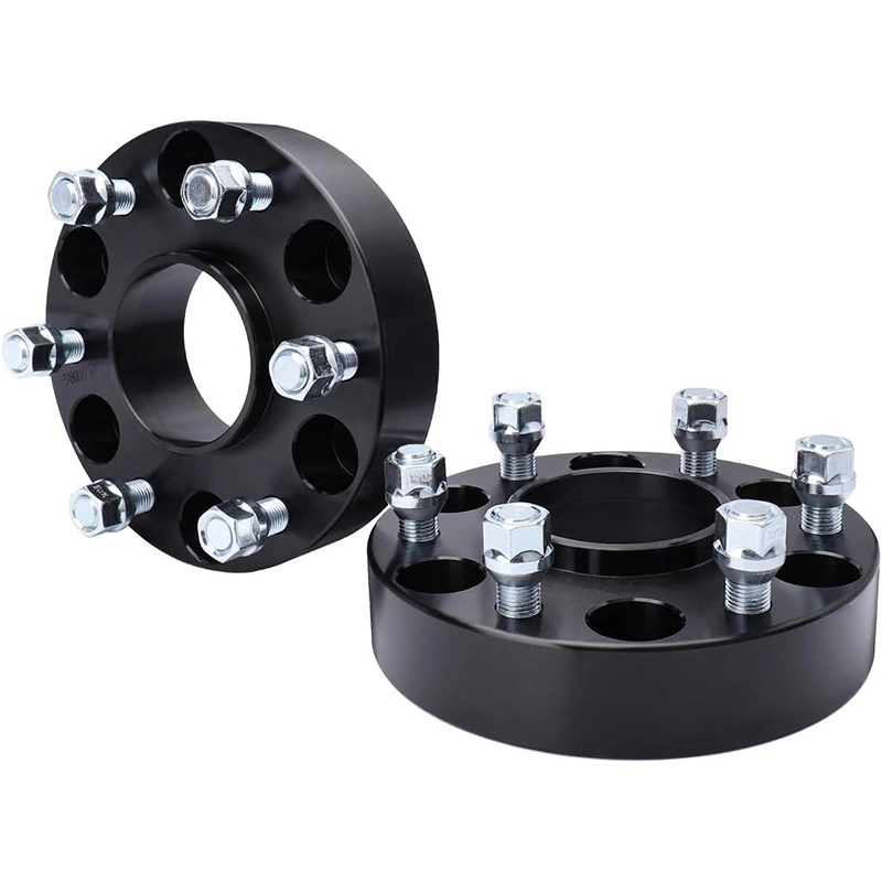
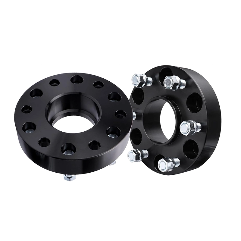
The spacer sits between the hub and the wheel. With the same wheel and tire, its thickness moves the wheel centerline and contact patch outward. It does not relocate the ball joints, strut top or other hard points that define the steering axis.
r₁ ≈ r₀ + sThis article uses outboard as the positive direction. The approximation assumes the same wheel, tire, ride height, steering axis and static alignment. It describes the shift, not a manufacturer-approved target.
If the original signed scrub radius is -8 mm and a 12 mm spacer moves the contact patch outward, the simplified result is +4 mm.
-8 mm + 12 mm = +4 mm
These numbers are an example only. They are not J&W test data or a recommendation for a vehicle.
You still need the original scrub radius or enough suspension and tire geometry to locate the steering-axis ground point. Spacer thickness tells you the approximate change when the other inputs remain fixed.
A lower-offset wheel can create the same scrub-radius shift
A spacer is one way to move the wheel outward. A wheel with less positive offset can place the wheel centerline in the same final position. If wheel width, tire geometry, ride height and suspension hard points are otherwise equal, the steering geometry responds to the final wheel and contact-patch position, not to whether the distance came from a spacer or the wheel's own offset.
This is why a fair comparison uses effective offset:
ETeffective = ETwheel - sA 10 mm spacer reduces effective positive offset by 10 mm. Use the same units for offset and spacer thickness.
The wheel spacer offset guide covers the calculation in detail. The scrub-radius page has a different job: it explains what the outward shift means at the steering axis.
A normal alignment reading can stay in range while scrub radius changes
Installing a flat spacer does not directly move the suspension pivots or turn the tie rod. Static toe, caster and camber may therefore remain close to their previous readings. At the same time, the tire contact patch has moved sideways relative to the steering axis.
A routine alignment printout may not list the final scrub radius. Bringing adjustable toe or camber back into specification also does not return the wheel centerline to its original location. Restoring the original static scrub-radius relationship usually requires restoring the relevant wheel and tire position, suspension geometry or both.
After a wheel-position change, record the before-and-after wheel specifications alongside the alignment results. That makes the geometry change visible even when the alignment machine does not report scrub radius.
Steering feel can change, but symptoms are not proof of one cause
Scrub radius creates a lever arm between forces at the tire and the steering axis. In a simplified ground-plane model, longitudinal tire force acting through that lateral distance can create steering torque.
Tsteer ≈ Fx × rThe relation shows why the same braking or traction force can create more steering disturbance when the lever arm is larger. Real steering response also depends on caster trail, compliance, assist tuning, tire construction and suspension motion.
Use symptoms to choose the next inspection, not to declare a diagnosis:
| Observation after the change | Could scrub-radius shift contribute? | Check separately before blaming it |
|---|---|---|
| More steering effort at parking speed | Possible, because the tire may sweep around a larger ground offset. | Tire pressure and size, steering assist faults, upper mounts and joint condition. |
| More steering kick over a one-sided bump | Possible, because the road force acts through a changed steering lever arm. | Tire condition, ball joints, tie rods, bushings, wheel damage and road surface. |
| Pull during uneven left-right braking | Possible. Scrub radius can influence how unequal longitudinal forces reach the steering. | Brake imbalance, tire grip, alignment, road crown and suspension damage. |
| More torque steer under acceleration | Possible on a driven steering axle, but scrub radius is only one input. | Driveshaft geometry, engine mounts, differential behavior, tire grip and alignment. |
| Speed-dependent vibration | Not the first explanation. Scrub radius can change how a disturbance is felt, but it does not create wheel imbalance. | Spacer seating, centering, wheel balance, runout, hardware and damaged surfaces. |
| Tire rub at full lock or compression | This is primarily a clearance result of the new wheel position. | Fender, liner, suspension, brake hose and body clearance through full motion. |
| Uneven tire wear | Scrub radius alone is not a sufficient diagnosis. | Toe, camber, pressure, worn joints, tire rotation history and vehicle loading. |
If vibration started immediately after installation, use the wheel spacer vibration checklist. That sequence checks mounting and centering faults before moving to broader chassis diagnosis.
Rear spacers do not normally change front steering scrub radius
Scrub radius is normally discussed at a steering axle. A spacer fitted only to a conventional non-steering rear axle changes rear track width, wheel position, clearance and the wheel-bearing lever arm. It does not move the front tire contact patches or the front steering axes.
That distinction matters when diagnosing a vehicle. If only rear spacers were installed and the steering wheel now vibrates, scrub radius is not a strong first explanation. Check wheel seating, centering, balance, runout and hardware at the changed axle, then inspect the rest of the vehicle as needed.
Rear-wheel-steering systems are an exception because the rear axle has its own steering geometry. Those vehicles require model-specific information.
Each front wheel has its own mirrored steering axis. Moving both contact patches outward changes the lever arm at both sides even though the vehicle remains visually symmetrical.
The separate wheel spacer and bearing guide explains the hub-load geometry that applies at both steering and non-steering axles.
Review the final wheel position before ordering a spacer
There is no universal scrub-radius limit that can be approved from spacer thickness alone. The useful workflow is to document the baseline, calculate the final position and keep the vehicle's operating context attached to the numbers.
- Record the axle and steering system.State whether the spacer is for the front, rear or both, and note any rear-wheel-steering system.
- Record the original wheel and tire.Include wheel width, diameter, marked offset, tire size and any change from the vehicle's original package.
- Calculate effective offset.Subtract spacer thickness from the wheel's positive offset using the same units.
- Separate shift from absolute scrub radius.The spacer gives an approximate outward shift. Absolute scrub radius still requires the original value or the suspension and tire geometry.
- Check physical fitment.Verify hub pilot, wheel center bore, PCD, mounting faces, hardware and clearance through steering and suspension travel.
- Document the reason for the change.Brake clearance, suspension clearance and stance goals can lead to different minimum-thickness decisions.
- Inspect and test after installation.Stop if there is contact, looseness, abnormal noise, pulling or vibration. Diagnose the symptom instead of treating it as normal.
Use the wheel spacer measurement worksheet for physical dimensions and the complete fitment guide for the hub, spacer, wheel and hardware stack.
Send the final wheel setup, not a spacer size copied from another car
Provide the vehicle and axle, wheel width and offset, tire size, hub dimensions, target clearance and proposed spacer thickness. J&W can discuss the spacer interfaces from that complete fitment set.
- SAE International: Functional Vehicle Dynamics Simulation, used to verify that scrub radius is among the steering parameters that affect dynamic torque, returnability and on-center feel.
- OZ Racing: The wheel, used for the wheel-offset definition.
- Eibach: PRO-SPACER, used to cross-check that wheel spacers increase track width and move wheel fitment outward.
Safety note: This page explains simplified static geometry. It does not establish a vehicle-specific spacer approval or replace the vehicle manufacturer's instructions, suspension data or inspection by a qualified automotive professional.