
Wheel fitment mechanics
Do Wheel Spacers Affect Wheel Bearings?
Spacer thickness moves the wheel outward. That changes the leverage at the hub, but it does not let anyone predict bearing life from thickness alone.
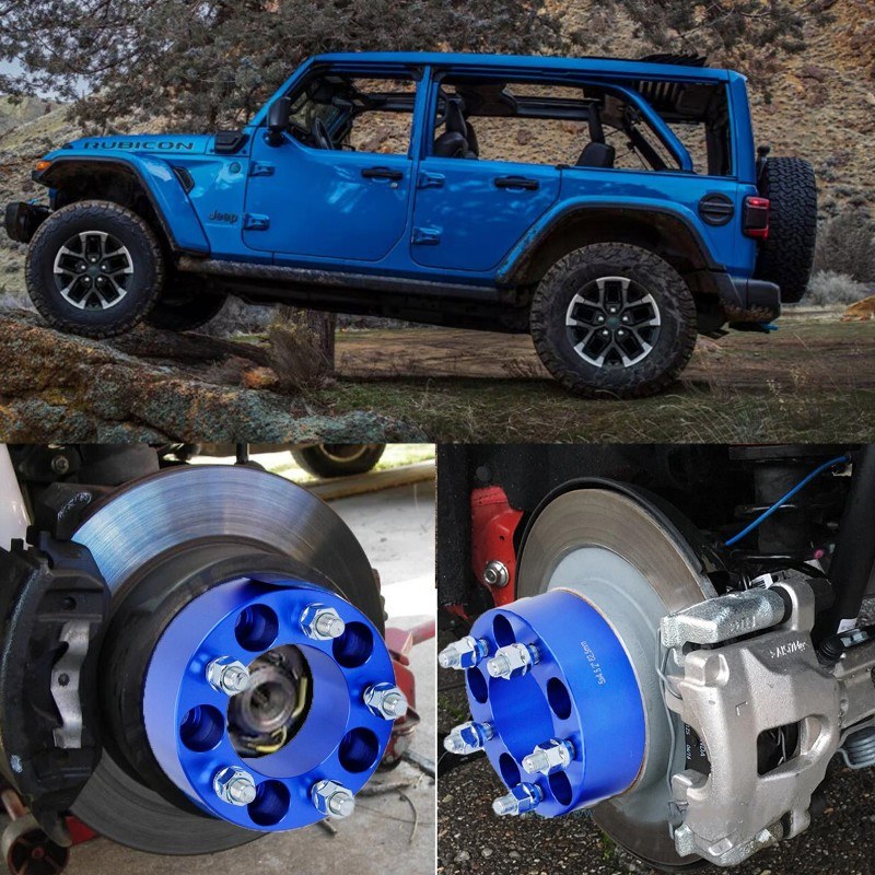
Yes, wheel spacers can affect the load applied to a wheel bearing because they move the wheel and tire farther from the bearing center. A thicker spacer creates a longer lever arm for the same tire force. That is a real mechanical change. It is not proof that every spacer will cause premature failure, and it is not enough information to calculate how long a particular bearing will last.
What actually changes at the hub
Look at the assembly from the front axle toward the wheel. The bearing supports the rotating hub. The wheel mounts to a face on that hub. The tire then applies vertical, cornering, braking and impact forces through the wheel back to the hub and bearing.
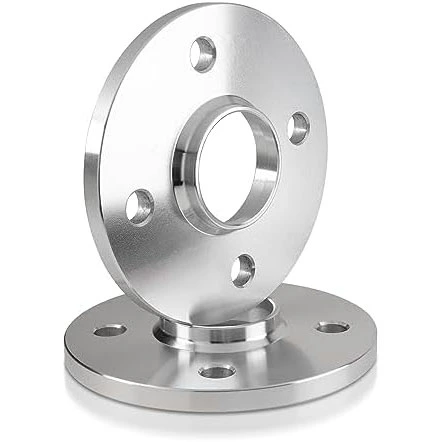
Adding a spacer places another part between the hub mounting face and the wheel mounting pad. The wheel moves outward by the spacer thickness. If the original distance from the bearing reference point to the wheel centerline is d, a simplified illustration gives a new distance of d + s, where s is spacer thickness.
M = F × distanceFor the same force F, increasing the distance increases the bending moment M in this simplified model. The equation shows the direction of change. It is not a vehicle-specific bearing-life formula.
The force is rarely constant in use. Cornering, a pothole, braking and tire grip can all change its size and direction. That is why a useful assessment starts with geometry but does not end there.
Spacer thickness and wheel offset describe the same outward move differently
Wheel offset describes the position of the wheel mounting surface relative to the wheel centerline. A spacer changes where the wheel mounting pad sits relative to the hub. In a simple fitment calculation, spacer thickness reduces effective positive offset by the same amount.
For example, adding a 15 mm spacer to a wheel that started at ET45 gives an effective position of ET30. The wheel moves 15 mm outward. The same result could come from selecting a wheel with 15 mm less positive offset, assuming wheel width and the rest of the geometry remain unchanged.
A factory wheel with a spacer and an aftermarket wheel with a different width and offset may place the tire centerline in different positions even when the spacer thickness is identical. Use the wheel spacer offset guide to calculate the final position.
More leverage is not the same as guaranteed bearing failure
The geometry tells us that moving the tire force outward can increase the moment applied around the bearing. It does not tell us that a bearing will fail after a certain distance, nor does it produce a universal safe spacer thickness.
Bearing life is a statistical engineering estimate that depends on load and operating conditions. Vehicle hubs also differ in bearing size, bearing arrangement, preload, sealing, lubrication, axle load and original wheel position. Two vehicles using the same spacer thickness can therefore have different load margins and service outcomes.
A small change on a lightly used road car is not the same duty cycle as a larger change on a heavy vehicle with oversized tires, repeated impacts or sustained cornering. The correct question is not simply, “Does a spacer affect bearings?” It is, “What final wheel position and operating load will this complete setup create?”
The variables that matter in a real fitment
Spacer thickness is one input. A useful review keeps the entire rotating package and the way the vehicle is used in view.
| Variable | Why it matters | What to record |
|---|---|---|
| Final wheel position | Sets the tire centerline relative to the hub and affects inner and outer clearance. | Wheel width, marked offset and spacer thickness. |
| Wheel and tire package | Diameter, width and mass influence rotational and impact loads. | Wheel size, tire size and any change from the original package. |
| Vehicle duty | Payload, towing, off-road impacts and track use create different load histories. | Normal use, maximum expected load and road conditions. |
| Hub and bearing condition | Existing wear, play or damage is not corrected by adding a spacer. | Inspection findings before the modification. |
| Mounting interfaces | Debris, interference or poor seating can create runout and movement. | Flat contact, pilot engagement and clearance around the brake assembly. |
| Hardware engagement | The wheel still needs the correct fastener type, seating profile and engagement. | Stud or bolt specification, seat type and available thread engagement. |
This table also explains why copying a spacer size from another vehicle is unreliable. A matching bolt pattern does not establish the same wheel offset, hub pilot, hardware, axle load or use case.
What hub-centric design changes, and what it does not
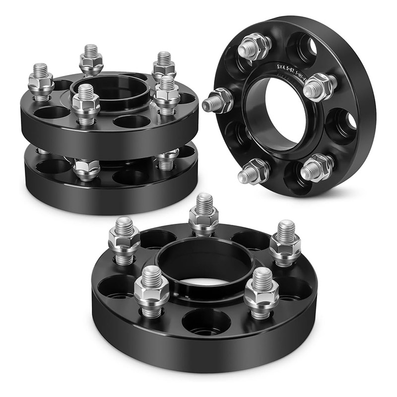
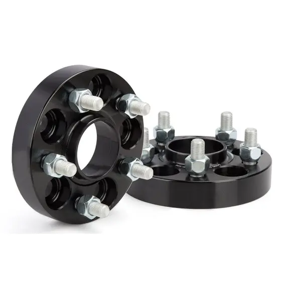
A hub-centric spacer includes locating geometry intended to match the vehicle hub pilot and the wheel center bore. When the dimensions and profiles match, that geometry helps locate the assembly concentrically during mounting.
It does not move the wheel centerline back toward the bearing. A 20 mm hub-centric spacer still moves the wheel outward by 20 mm. Centering quality and load geometry are related to the same assembly, but they answer different questions.
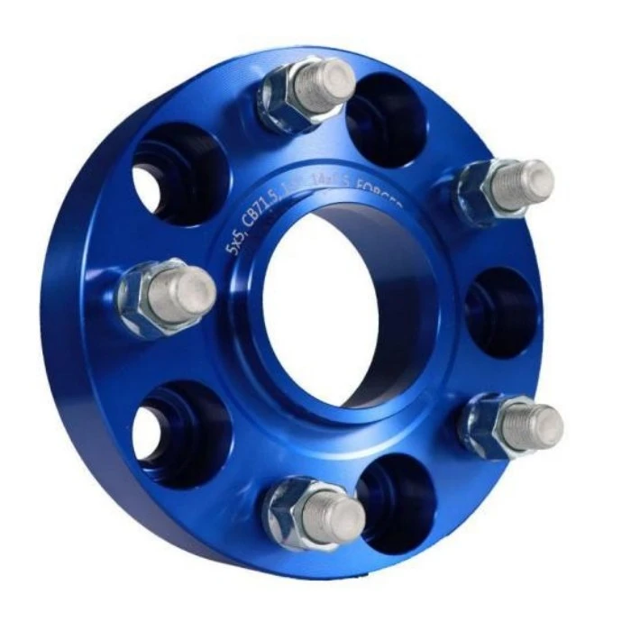
First, verify that the spacer can sit flat and locate correctly. Second, evaluate the final wheel position and clearance. A part can be well centered yet still create an unsuitable outward position for a particular vehicle.
Review the wheel-to-hub stack before choosing thickness
Start with the problem the spacer is meant to solve. Brake-caliper clearance, inner tire clearance and visual stance are different targets. The required thickness should come from a measured gap, not from a product photo or another owner's setup.
For a useful J&W fitment discussion, provide the complete front and rear data where they differ:
- Identify the vehicle and axle.Include model, year, trim and whether the measurements are for the front or rear.
- Record the hub interface.Measure PCD, hub pilot diameter, pilot height and the mounting surface around the brake disc.
- Record the wheel interface.Provide wheel width, diameter, offset, center bore, mounting-pad recesses and fastener-seat type.
- Measure the limiting clearance.Show where the wheel or tire is closest to the caliper, suspension, fender or bodywork.
- Define the requested change.State the smallest thickness that solves the measured clearance problem and the quantity required.
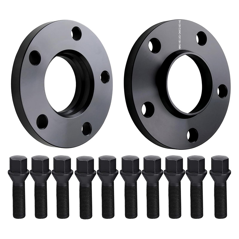
- Confirm the hardware path.For slip-on systems, check the longer stud or bolt requirement. For bolt-on systems, check original stud projection and wheel back-pad pockets.
The complete wheel spacer fitment guide and measurement worksheet cover these dimensions in more detail.
How to reduce unnecessary load and installation risk
No checklist can turn an unsuitable modification into a suitable one, but several decisions prevent avoidable problems.
- Use the minimum thickness that solves the measured need. Extra thickness adds outward movement without adding clearance value once the interference is already resolved.
- Calculate the final effective offset. Include wheel width and offset instead of treating spacer thickness as a stand-alone number.
- Keep tire and wheel changes in the same calculation. A wider or heavier package can change both clearance and operating load.
- Check both mounting faces. The hub-to-spacer and spacer-to-wheel contacts must be clean, flat and free of interference.
- Use the specified hardware and tightening procedure. Follow the vehicle, wheel and spacer instructions applicable to the exact setup. Recheck according to those instructions.
- Do not install over an unresolved symptom. Bearing noise, wheel play, damaged threads or persistent vibration requires diagnosis first.
Our wheel spacer installation guide focuses on surface preparation, seating and hardware checks. If a vibration begins after installation, use the vibration diagnostic sequence instead of assuming the bearing is the first cause.
Common wheel-spacer claims need more context
Too absolute. A spacer changes geometry, but bearing outcome depends on the final position, loads, duty cycle, bearing design, condition and installation.
Incorrect. Hub-centric geometry addresses location and fit. It does not cancel the outward movement created by spacer thickness.
Incomplete. Even a thin part must match the hub, wheel, hardware and available clearance. Thin slip-on designs can also reduce the pilot engagement available to the wheel.
Quality matters, but a well-made part with the wrong dimensions or an unsuitable final wheel position is still the wrong fitment.
Send the complete stack, not spacer thickness alone
Share the vehicle, wheel specification, hub dimensions, measured clearance, target thickness and expected use. J&W can then discuss a standard or custom wheel spacer configuration from the actual interfaces.
- SKF: Size selection based on rating life, used to verify that bearing-life assessment is load and operating-condition dependent and statistical.
- Eibach: PRO-SPACER technical and fitment information, used to cross-check spacer-system and fitment principles.
Safety note: This article explains general geometry and fitment principles. It does not replace vehicle-specific engineering approval, the vehicle manufacturer's instructions or inspection by a qualified automotive professional.