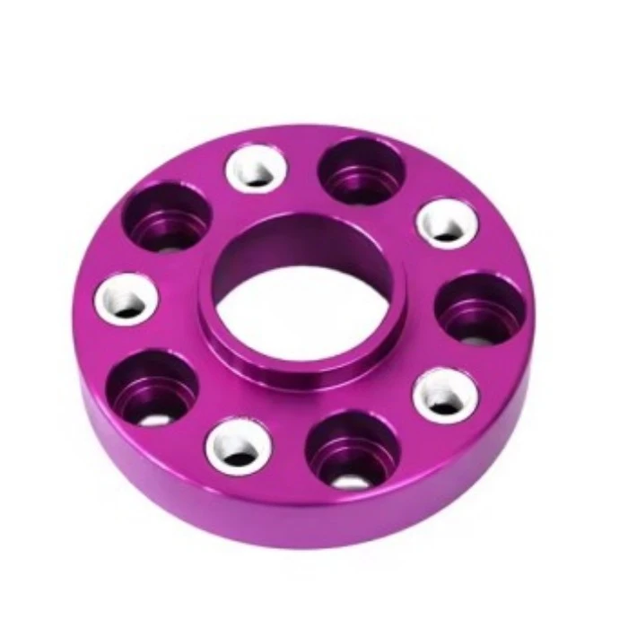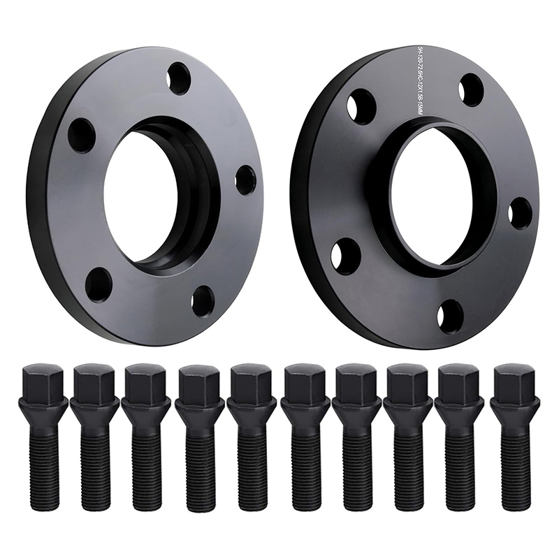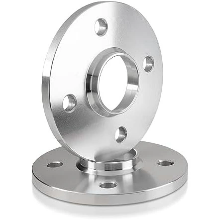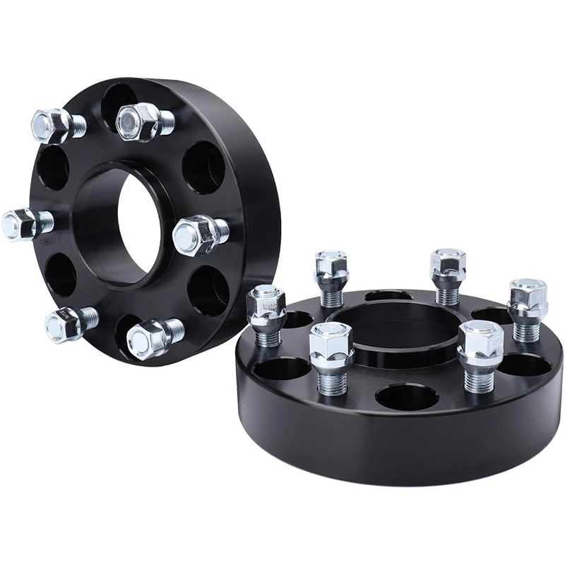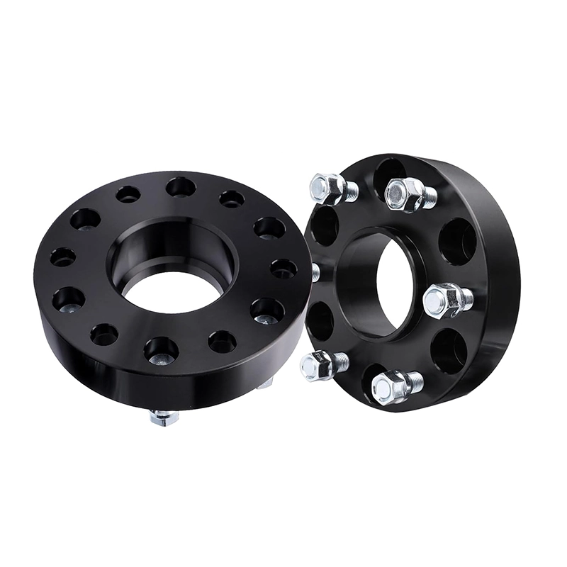

Diagnose the new interface before blaming the new part. A spacer can reveal a centering, seating, hardware or wheel-and-tire problem that was not obvious before installation.

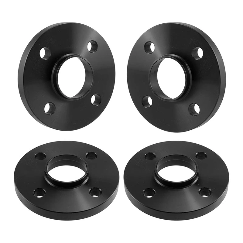
Vibration after fitting wheel spacers is a fault signal, not a normal break-in effect. If the vehicle was smooth before the work, begin with what changed: the hub-to-spacer face, spacer-to-wheel face, centering geometry, fasteners and clearances. If those pass inspection, move outward to the wheel, tire and vehicle.
Stop driving when vibration comes with movement, noise or contact
Severe shake, a loose-wheel sensation, clicking, knocking, rubbing, braking changes or sudden steering changes require an immediate inspection. Do not keep tightening by feel or continue a road test to see whether the symptom disappears.
01Record when and where the vibration appears
A useful diagnosis begins with a repeatable description. Note whether the vibration appeared immediately after the spacer installation, after a wheel or tire change, after the fasteners were rechecked, or only after some driving. Record the speed range, whether braking or steering changes it, and whether it is felt mainly through the steering wheel, seat or floor.
Michelin lists tire imbalance and steering or suspension faults among the causes of vehicle vibration and advises professional inspection when vibration appears. Tire Rack’s vehicle vibration diagnosis chart uses symptom location and recent vehicle changes as starting points, not as final proof of one failed part.
Was the vehicle smooth immediately before the spacer work? A clear before-and-after baseline narrows the search. A pre-existing vibration that becomes easier to feel after a wheel change needs a broader wheel, tire, hub and suspension diagnosis.
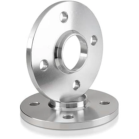
02Confirm that both mounting faces sit fully flat
A thin layer of rust scale, dirt, trapped paint, a brake-disc retaining clip or a damaged edge can tilt the spacer by an amount that is difficult to see. The wheel then rotates around an axis that is not perfectly aligned with the hub.
Remove the wheel and spacer. Inspect the hub face, hub pilot, both spacer faces and the wheel back pad under good light. Clean loose rust and debris without damaging the hub, brake components, threads or sensors. Place the spacer on the bare hub and check for rocking or a visible gap. Repeat the contact check between the wheel and spacer.
Eibach’s System 6 installation instructions require the hub center and wheel surfaces to be clean and direct the installer to confirm that the spacer sits without play, its holes coincide and its chamfer faces the hub. If the dry-fit check is unsatisfactory, installation stops.
If the spacer or wheel will not sit flat by hand, tightening the assembly is not a correction. Find the obstruction or dimensional mismatch first.
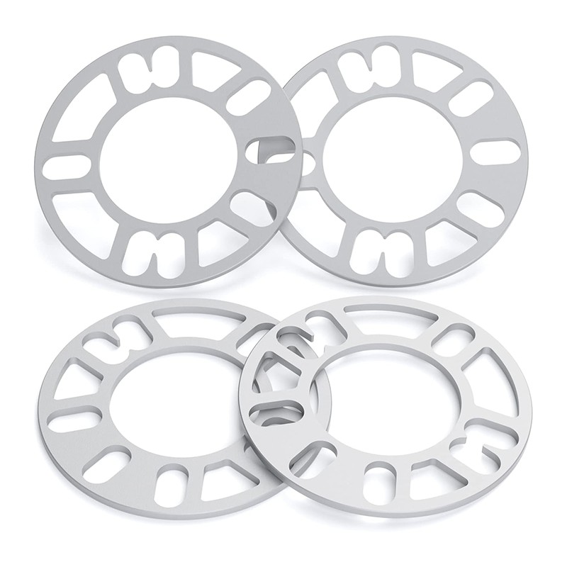
03Trace the complete centering path
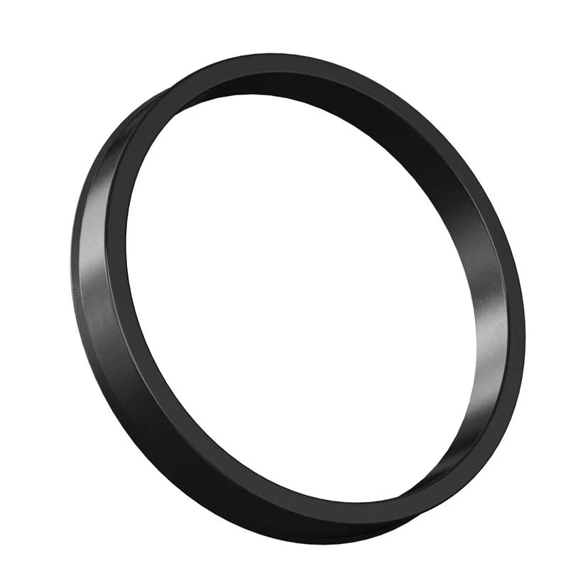
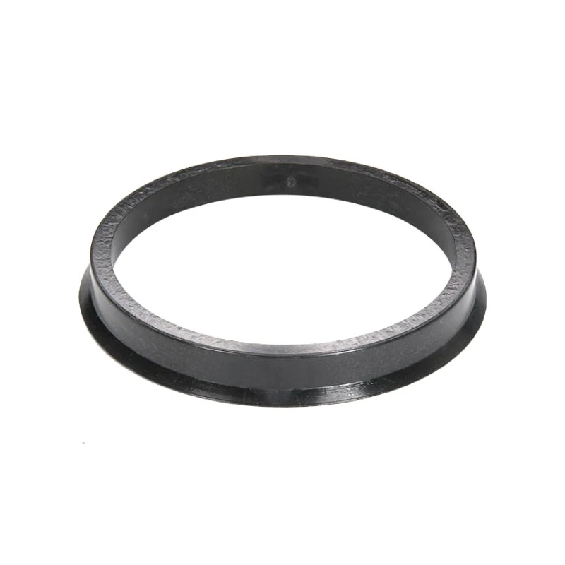
“Hub-centric” describes a geometry, not a guarantee. The vehicle hub pilot must fit the spacer bore, and the spacer’s wheel-side lip must fit the wheel center bore. The lip height, lead-in chamfer and any radius at the hub or wheel also need room to seat.
A bore that is too small will not seat. A bore that is too large cannot locate on that pilot. A lip that is too short may not reach the wheel bore; one that is too tall may bottom inside the wheel before the back pad reaches the spacer face. Paint, corrosion and damage can create the same symptoms as an incorrect nominal size.
Hub-centric parts help locate the rotating assembly only when the dimensions match. They do not correct wheel imbalance, a bent wheel, runout, debris or incorrect tightening. Lug-centered systems are also application-dependent; they require the correct fastener seats and a controlled centering procedure rather than a blanket assumption that every such design will vibrate.
Use the wheel spacer fitment guide to verify PCD, hub bore, wheel center bore, lip geometry and hardware as one stack.
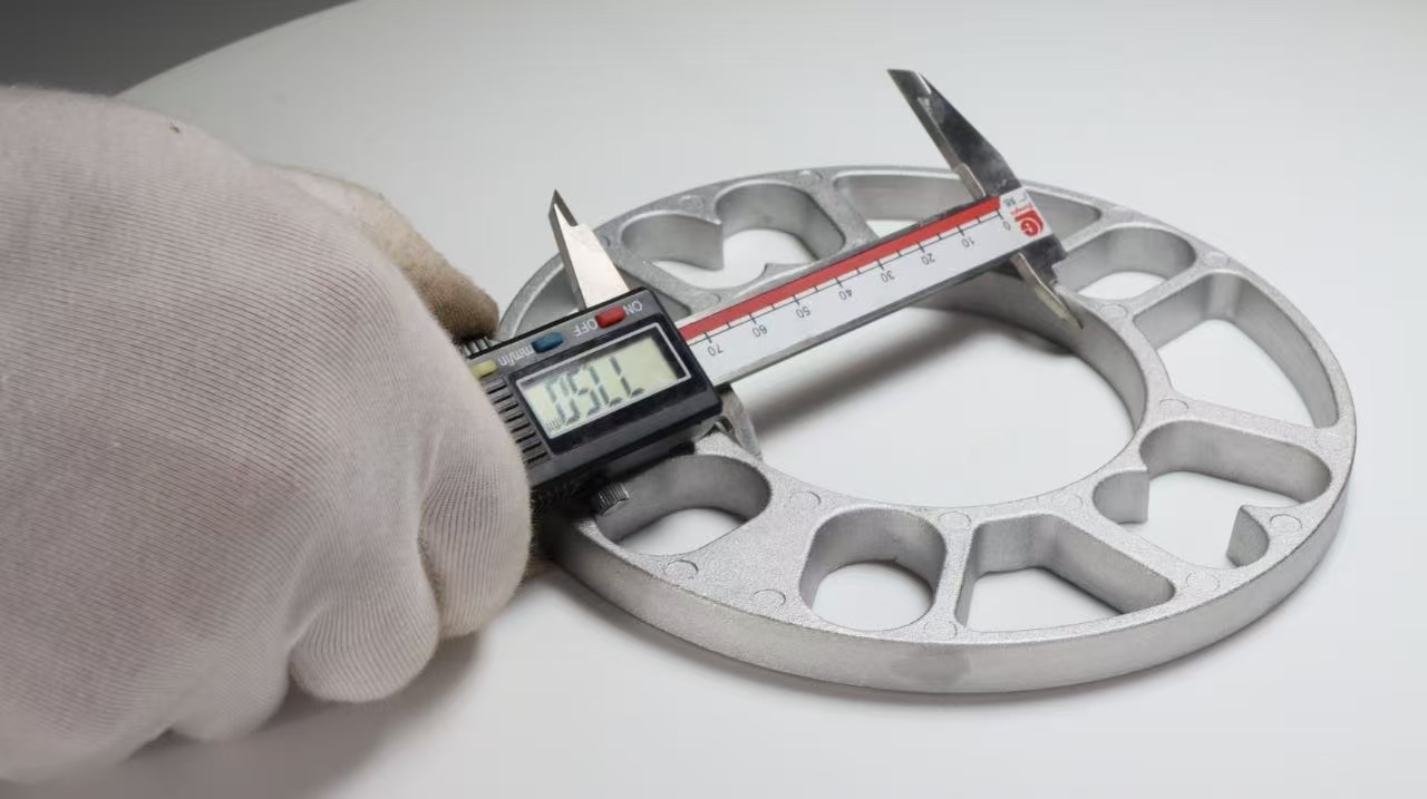
Nominal fitment data must agree with the parts in hand
Measure clean metal surfaces and compare the hub, spacer and wheel as a connected stack. A vehicle application name alone cannot confirm the bore, lip, chamfer or aftermarket-wheel geometry.
04Check the fastener system, not only the torque value
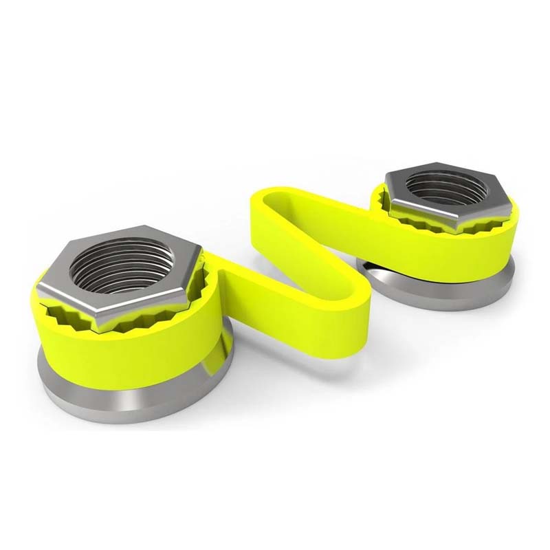
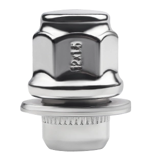
Wheel bolts and lug nuts must match the thread, seat shape, usable length and installation method. A correct torque number cannot rescue a mismatched conical or ball seat, a bottomed bolt, damaged threads, inadequate engagement or a wheel that was never centered and seated evenly.
- Hand-start every fastener.Each fastener should engage the correct thread freely. Binding is a stop signal, not an invitation to use a longer handle or impact tool.
- Bring the assembly into contact evenly.Use the cross or star pattern specified for the vehicle and spacer system so one side is not pulled down before the other.
- Apply final torque with a calibrated wrench.Use the vehicle workshop manual, wheel instructions and spacer instructions for the exact application. There is no universal wheel-spacer torque.
- Follow the product’s recheck interval.Inspect sooner whenever vibration, noise, looseness or contact appears.
The Eibach instructions require a torque wrench for final tightening and state that the vehicle manufacturer’s workshop manual takes priority if instructions conflict. They also include system-specific thread-engagement requirements; use the instructions for the exact part rather than copying a number from another vehicle or thread.
Repeatedly adding torque without finding the cause may hide movement temporarily or damage the fastener system. Remove, inspect and identify why the assembly did not remain seated.
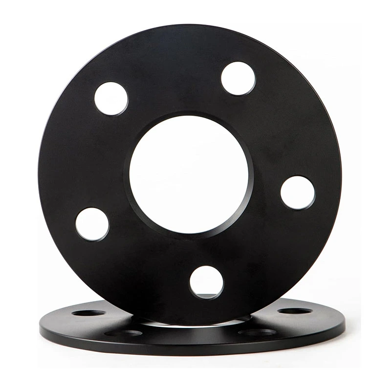
05Look for interference behind the wheel
On some bolt-on systems, original studs or spacer attachment bolt heads can project beyond the spacer face. The wheel then needs correctly positioned pockets with enough depth. If the wheel back pad contacts the hardware first, the wheel cannot clamp flat against the spacer.
H&R’s TRAK+ application note explains this wheel-pocket requirement for relevant DRM and DRA systems. Measure stud or bolt-head projection and compare it with the actual wheel-pocket depth and location.
After assembly, rotate the raised wheel through a complete revolution and inspect nearby brake, ABS, suspension and body components. Eibach calls for a free-rotation check before road testing. Steering sweep and suspension travel also matter: contact may occur only near full lock or over a bump.
- Bright witness marks or polished spots suggest recent contact.
- A repeated scrape linked to wheel rotation is not a balance problem.
- Tire rub may appear only during steering or suspension compression.
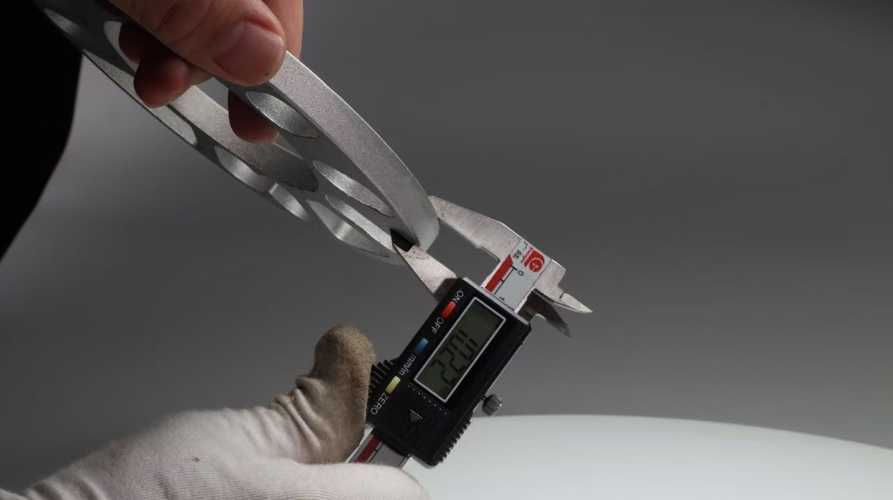
06Separate spacer faults from wheel, tire and vehicle faults
If the spacer seats flat, centers correctly, clears the wheel and uses the right hardware, do not keep replacing spacer parts at random. Check the wheel-and-tire assembly and the vehicle baseline.
Michelin’s vibration guidance identifies out-of-balance tires and steering or suspension faults as possible causes. Its wheel-balancing guidance notes that imbalance may be felt through the steering wheel or through the seat and floor, especially at particular speeds.
Tire Rack’s mounting and balancing procedure also calls for clean hub contact, correct lug torque and secure seating. When rebalancing does not resolve a speed-dependent vibration, it recommends checking tire and wheel runout.
Use a controlled comparison
A qualified installer can return the vehicle to the last known smooth, approved wheel configuration and compare the symptom. Change one variable at a time. Swapping several wheels, spacers and fasteners at once destroys the evidence needed to identify the cause.
Check the spacer if the vehicle-side installation is correct
Inspect both faces and the center bore for damage, raised material or visible machining defects. A shop can check lateral and radial runout at the installed assembly instead of guessing from appearance.
07Use this diagnostic order
Start with the safest, fastest checks that are closest to the recent installation. Escalate to measured wheel-and-tire diagnosis only after the assembly is known to be secure and seated correctly.
| Order | Inspect | What passes | Action if it fails |
|---|---|---|---|
| 1 | Noise, looseness, rubbing and braking or steering change | No movement, contact or sudden control change | Stop road use and inspect before continuing |
| 2 | Hub, spacer and wheel mounting faces | Clean, undamaged and fully flush at both interfaces | Remove debris or correct the interference; do not pull flat with fasteners |
| 3 | Hub bore, spacer bore, lip, wheel bore and chamfers | Correct location without play or bottoming | Replace the incompatible part or correct the verified fitment |
| 4 | Fastener thread, seat, usable length, engagement and tightening sequence | Correct hardware, smooth hand engagement and specified torque | Replace mismatched or damaged hardware and reinstall correctly |
| 5 | Stud projection, bolt-head clearance and wheel pockets | Wheel back pad contacts the spacer fully | Use a compatible approved system; never clamp over interference |
| 6 | Rotational and dynamic clearance | No contact through rotation, steering and suspension movement | Revise spacer thickness or the fitment package |
| 7 | Wheel balance, tire condition and wheel/tire runout | Assembly meets the vehicle or service specification | Correct through professional wheel-and-tire service |
| 8 | Hub, bearing, brake, steering and suspension condition | No measured fault or looseness | Repair the vehicle fault before judging spacer performance |

08Prevent the same problem on the next installation
Fitment data should describe both sides of the spacer, not just the vehicle model. Record the axle, hub PCD, hub pilot, wheel PCD, wheel center bore, lip and chamfer geometry, spacer type, thickness, fastener thread and seat, usable length, stud projection and wheel-pocket depth.
Photograph the clean hub face, wheel back pad and dry-fit contact before final assembly. Keep the part number, drawing revision, hardware specification, torque source and recheck interval with the work record. This makes a repeat installation easier to verify and a vibration complaint easier to diagnose.
For a clearer distinction between locating systems, see hub-centric vs lug-centric wheel spacers. For product styles and fitment discussions, use the wheel spacer range as a starting point and confirm the final application with measured vehicle and wheel data.
Wheel spacer vibration FAQ
Can wheel spacers cause vibration?
They can introduce vibration when a spacer does not sit flat, does not center correctly, uses incompatible hardware, interferes with the wheel, or changes clearance. Vibration can also come from the wheel, tire, hub, brake or suspension, so the installation timing is a clue rather than proof.
Will hub-centric wheel spacers fix vibration?
Only when the vibration is caused by a centering problem that the correct hub-centric geometry resolves. The spacer bore, hub pilot, spacer lip, wheel center bore and chamfers must all be compatible. A hub-centric label cannot correct debris, uneven seating, wrong hardware, wheel imbalance or runout.
Why does the vibration appear only at highway speed?
Rotational imbalance and runout commonly become more noticeable within certain speed ranges. That pattern points toward a rotating assembly, but it does not identify the spacer by itself. Check spacer seating and centering first if the symptom began after installation, then have wheel balance and runout inspected if those checks pass.
Can uneven wheel-fastener tightening cause vibration?
Uneven or incorrect tightening can keep the wheel or spacer from seating uniformly. Hand-start every fastener, use the specified cross pattern and stages, and apply the application-specific final torque with a calibrated torque wrench.
Can I keep driving if the vehicle vibrates after spacer installation?
Do not treat new vibration as a normal break-in effect. Stop as soon as it is safe, especially if the vibration is severe or accompanied by clicking, knocking, looseness, rubbing, braking changes or steering changes. Inspect the installation before further road use.
Safety note: This article is a diagnostic framework, not a substitute for the vehicle workshop manual or the instructions supplied with the exact wheel and spacer system. Wheel fastening and vibration diagnosis should be completed or verified by a qualified technician.