
Wheel spacer bolt pattern: read PCD before you check fit
The label 5×114.3 contains two facts, not one. It identifies five mounting positions on a 114.3 mm circle. It says nothing about the bore, thread, thickness or which side of an adapter the pattern belongs to.
+
1 CIRCLE
How to read a wheel spacer bolt pattern
PCD means Pitch Circle Diameter. It is the diameter of the circle that passes through the centers of the mounting holes or studs. Wheel maker OZ Racing defines the dimension this way and pairs it with the number of holes. [1]
The number of equally spaced fastener positions. Depending on the interface, these may be clearance holes, threaded holes or studs.
The separator means “positions on a circle.” It does not mean that the two numbers can be checked independently.
The diameter of the theoretical circle through the center of every position, not the distance between random hole edges.
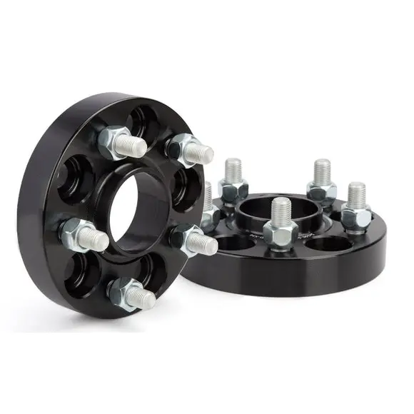
That makes 5×114.3 a precise geometric label. It is not another name for “five-lug.” A 5×100, 5×112, 5×114.3 and 5×115 wheel spacer may look similar in a small product photo, but the hole centers occupy different circles.
Close numbers are still different patterns. Do not force a 5×114.3 spacer over a 5×115 hub, elongate a hole or assume the fasteners will center the mismatch. A part that does not align freely needs the correct specification, not more tightening force.
PCD also has no built-in vehicle meaning. The same pattern can appear across different makes, model years and axles while the hub bore, thread, brake package and wheel geometry differ. Use PCD as one field in the complete wheel spacer fitment sequence, not as a vehicle application approval.
The bolt circle is invisible, but its center line is exact
The useful reference is the center of each fastener position. Hole diameter, countersinks and chamfers can make edge-to-edge measurements misleading. The diagram below separates the hole centers from the surrounding features.
How to measure the PCD without guessing from the edges
Four, six and eight-lug patterns
Choose two positions that lie directly opposite each other and measure from the center of one to the center of the other. That distance is the PCD. If the studs or holes make the centers difficult to reach, use a suitable PCD gauge, template or controlled drawing instead of estimating across angled edges.
Five-lug patterns
A five-lug pattern has no opposite pair. One repeatable geometry method measures the straight-line distance between two adjacent hole centers. That distance is a chord of the pitch circle. If the chord is called c, the PCD can be calculated as follows:
PCD = c ÷ sin(36°)

≈ c × 1.701
The 36° angle is half of the 72° spacing between adjacent positions in a five-hole circle. This formula is exact geometry. The answer is only as good as the center-to-center measurement.
For example, an adjacent-center chord of about 67.2 mm calculates to about 114.3 mm. This is a mathematical illustration, not a reason to round an uncertain part into a known pattern. A small center-location error gets multiplied by the formula.
A general check for any evenly spaced pattern
PCD = c ÷ sin(180° ÷ n)
Here, c is the adjacent center-to-center chord and n is the number of equally spaced positions. Use it as a cross-check. Production approval should still rely on the part drawing, a verified application or suitable inspection equipment.
Do not mix measurement conventions. “Outside to outside,” “inside to outside” and center-to-center readings produce different numbers unless hole diameter and direction are handled correctly. Record exactly which features were measured.
The wheel spacer measurement guide covers hub, wheel, clearance and hardware measurements that must accompany the PCD.
A spacer has one pattern relationship; an adapter has two
A wheel spacer primarily moves the wheel outward and normally keeps the same bolt pattern. A PCD adapter can also convert the pattern. That difference changes how the part should be named, drawn and checked.
- Hub PCD and fastener count
- Hub pilot and spacer inner bore
- Vehicle stud or bolt interface
- Inboard relief and mounting face
- Wheel PCD and fastener count
- Wheel bore and spacer locating lip
- Spacer stud or threaded-hole interface
- Wheel back-pad and pocket clearance
Write a conversion as vehicle pattern → wheel pattern. The arrow prevents a supplier, inspector or installer from reversing the interfaces. If both sides are 5×114.3, say so. If the part converts 5×100 to 5×112, label which side is which rather than writing both patterns in an unlabeled note.
Product naming is not perfectly consistent. Some same-PCD bolt-on products are called “wheel spacer adapters” because the part bolts to the hub and supplies another set of studs. The title is not enough to decide whether the PCD changes. Read the two-sided drawing.

One label should not carry the whole specification
J&W currently lists a PCD 6×139.7, CB95.1 wheel spacer adapter. The listing also separates thread options and thickness. That structure matters: PCD, center bore, thread and thickness describe different features.
The listing is a product example, not a universal application chart. Vehicle, axle, wheel and hardware still need confirmation.
Matching PCD does not mean matching holes
A PCD label fixes the angular and radial position of the fastener centers. It does not define the feature around each center. Two parts can both be marked 5×114.3 and still require different hardware or fail to assemble.
| Feature | What PCD tells you | What must be specified separately |
|---|---|---|
| Hole count and position | Number of positions and their pitch-circle diameter | Nothing further for the basic circle, but orientation and any dual-pattern layout must be clear |
| Clearance hole | Its center position only | Hole diameter, counterbore, countersink, chamfer and fastener-head clearance |
| Threaded hole | Its center position only | Thread diameter, pitch, usable depth, entry and seat arrangement |
| Pressed stud | Its center position only | Stud thread, knurl diameter, knurl length, head geometry and installed projection |
| Centering feature | Nothing | Vehicle-side center bore, wheel-side lip, height, chamfer and radius clearance |
| Spacer function | Nothing about wheel position | Thickness, wheel offset, inner and outer clearance, and original hardware projection |
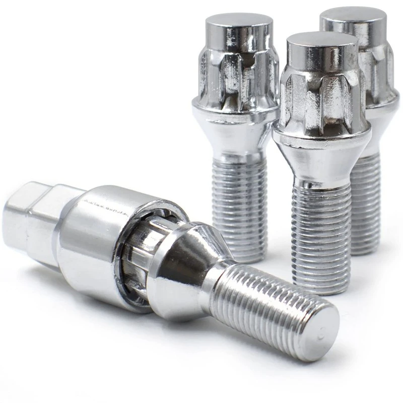
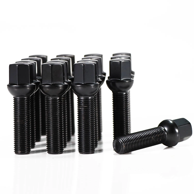
Seat geometry deserves special attention. A conical seat, ball seat and flat seat are not interchangeable merely because the thread and PCD match. On a bolt-on spacer, the hardware attaching the spacer to the hub may also differ from the hardware attaching the wheel to the spacer.
The same separation applies to center bore. A 5×114.3 spacer does not reveal whether its bore or lip fits the hub and wheel. Keep the adjacent wheel spacer center-bore guide with the drawing review so the bolt circle and centering path are checked together.
A bolt-pattern verification sequence that exposes bad assumptions
- Confirm the exact vehicle interface. Record make, model, year, market, trim and axle. Note hub, brake or stud changes. A database value is a lead, not proof of the physical vehicle.
- Confirm the exact wheel interface. Record the wheel manufacturer and part number. Do not assume an aftermarket wheel shares every hub dimension with the original wheel.
- Count the fastener positions. Separate functional holes from machining, access or weight-reduction holes. A spacer face can contain more openings than its PCD count.
- Measure or verify the circle. Use opposite centers for even patterns or a controlled five-lug method. Compare the result with the approved pattern, not the nearest familiar number.
- Label both sides. Record vehicle-side PCD and wheel-side PCD even when they are identical. Add center bore, lip and hardware for each interface.
- Inspect the delivered part. Check the part number and drawing revision. Confirm that holes, studs, threads and center features correspond to the approved specification.
- Dry-fit without force. The spacer must align on the hub and the wheel must align on the spacer. Both mounting faces need full contact before the correct tightening procedure begins.
Eibach's System 6 instructions require a check of the hub center and bolt pattern, followed by the same check between the wheel and spacer. The instructions say to stop when the fit is unsatisfactory. [2]
A free dry fit does not by itself approve the installation. It must be followed by the correct product instructions, hardware, torque, rotation and clearance checks. Never use a power tool or fastener load to hide a pattern error.
Send a two-sided pattern record, not “five-lug spacer”
For a standard wheel spacer enquiry, record the same PCD on both sides only after confirming that the hub and wheel match. For a converting adapter, state the direction clearly.
| Specification field | Vehicle side | Wheel side |
|---|---|---|
| PCD | Fastener count × hub pitch-circle diameter | Fastener count × wheel pitch-circle diameter |
| Centering | Hub pilot diameter, usable height and base profile | Wheel center bore, entry chamfer and available depth |
| Hardware | Stud or bolt thread, seat and existing projection | Required stud or threaded hole, seat and usable engagement |
| Faces and clearance | Hub-face relief, disc screw, clips and nearby components | Back-pad flat area, pockets, brake clearance and wheel offset |
| Traceability | Vehicle, year, trim, market and axle | Wheel brand, part number, size and photos of the back pad |
Add target thickness and the clearance measurements behind it. If any field is unknown, mark it unknown. That is more useful than filling a drawing with dimensions copied from a similar vehicle or wheel.
Best drawing label: “Vehicle side A → Wheel side B,” followed by PCD, center diameter, hole or stud type, thread, seat, thickness and critical relief dimensions. This reduces reversal errors during quotation, sample approval and incoming inspection.
Browse J&W's wheel spacer range for same-pattern applications or the wheel spacer adapter range when two interfaces need to be compared.
Wheel spacer bolt-pattern questions
What does 5×114.3 mean on a wheel spacer?
It means the wheel spacer has five equally spaced fastener positions on a 114.3 mm pitch-circle diameter. It does not state the center bore, thread, hole type, thickness or vehicle approval.
Is a five-lug wheel spacer universal?
No. Five-lug patterns include different PCD values, and a correct PCD still does not confirm the center bore, hardware, thickness or wheel-side clearance. Match the complete application and both mounting interfaces.
How do I measure a five-lug wheel spacer bolt pattern?
A five-lug pattern has no directly opposite hole. A controlled PCD gauge, template or drawing is the safer method. If adjacent hole centers can be measured accurately, divide that center-to-center chord by sin 36 degrees, which is approximately the same as multiplying by 1.701.
Can a 5×114.3 wheel spacer fit a 5×115 hub?
Do not treat them as interchangeable. The pitch-circle diameters differ. The part must align with the specified hub and wheel pattern without force, modification or tightening the fasteners to pull it into position.
What is the difference between a wheel spacer and a PCD adapter?
A wheel spacer primarily moves the wheel outward and normally retains the same bolt pattern. A PCD adapter also changes the bolt pattern, so its vehicle side and wheel side must be specified separately. Product naming varies, so confirm the drawing.