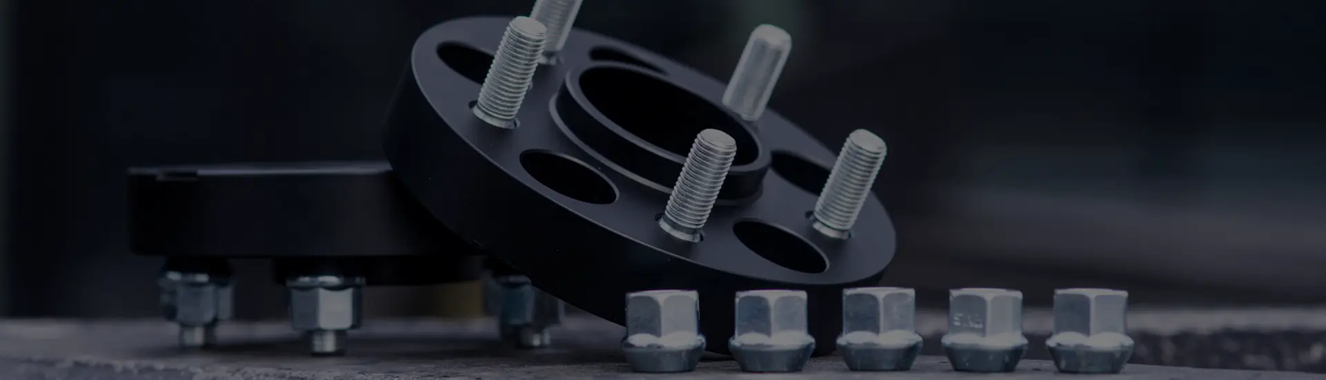

The label matters less than the complete fit
The difference is the reference used to center the wheel-spacer assembly. To judge either design, follow the geometry from the vehicle hub all the way to the wheel.
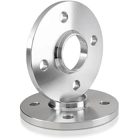
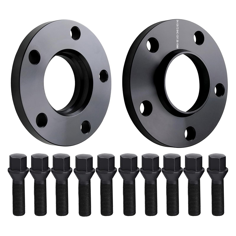
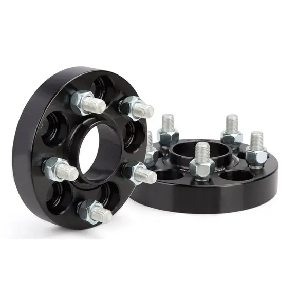
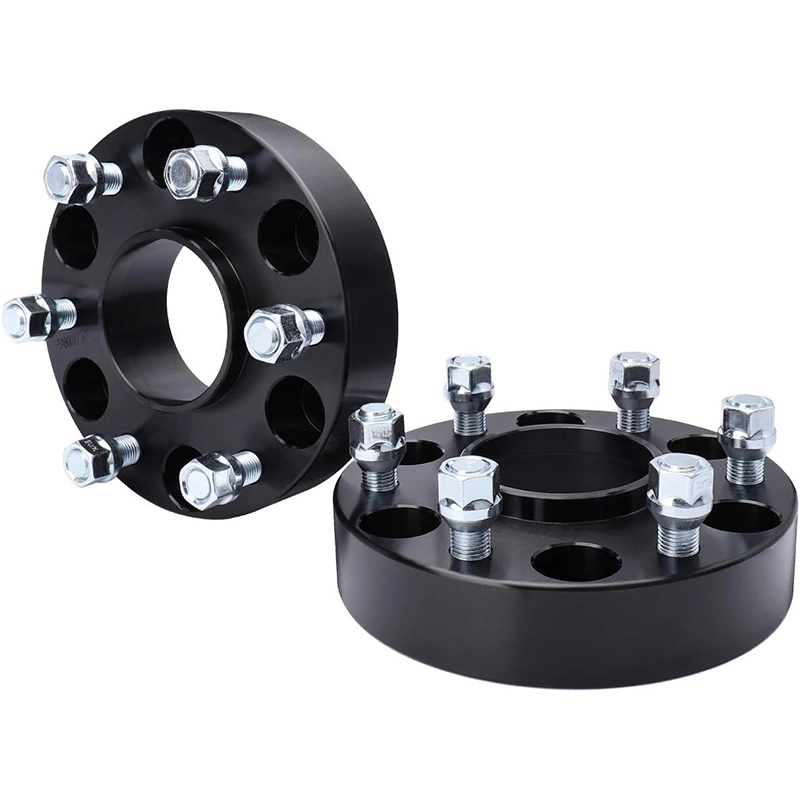
A hub-centric spacer uses matched center-pilot geometry to locate the assembly. A lug-centric arrangement relies on the wheel fastener seats to bring the assembly onto center during tightening. Hub-centric is usually easier to install repeatably, but the word on a listing proves nothing unless both sides of the spacer match the actual hub and wheel.
The difference is how concentricity is established before final clamp
Both designs still need compatible fasteners and sufficient clamp. The words hub-centric and lug-centric describe how the wheel is positioned around the hub axis while the joint is assembled.
Pilot geometry provides the center
The spacer fits over the vehicle hub pilot. The wheel then locates on the spacer's outboard pilot, or on another centering arrangement explicitly approved for that wheel. The pilot controls radial position while the fasteners are tightened.
Fastener seats establish the center
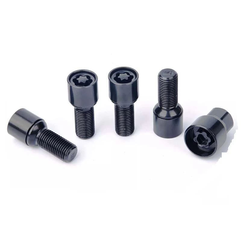
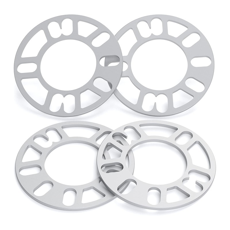
The center opening does not provide a close locating fit. Correct conical, ball or other designed seats bring the wheel into position as the fasteners are tightened evenly in the specified sequence.
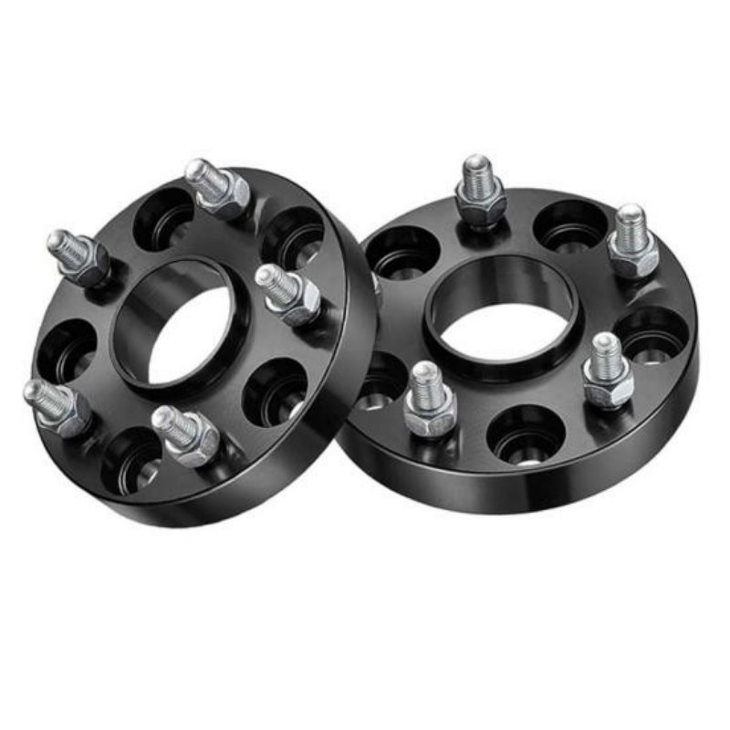
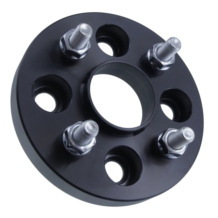
Neither term identifies the bolt pattern, spacer thickness, fastener thread or wheel-seat profile. It also does not say whether the spacer is slip-on or bolt-on. Those are separate fitment decisions. A slip-on or bolt-on wheel spacer can include hub-centering features, but the two attachment formats use different hardware paths.
Hub-centric fit is a four-interface chain, not one center-bore number
A spacer sits between two parts. Its inboard side must mate with the vehicle hub; its outboard side must mate with the wheel. Checking only the spacer's center bore covers half the problem.
Swipe the diagram to follow the complete centering chain.
This is why an application cannot be approved from "5-lug hub-centric spacer" alone. The wheel spacer fitment guide covers PCD, thickness, offset and hardware after the center interfaces have been identified.
The pilot locates the assembly; the preloaded joint provides the clamp
Hub-centric explanations often say the center lip "carries the vehicle weight" while the bolts do nothing but hold the wheel on. That wording is too crude for a bolted wheel joint. In a correctly tightened assembly, the fasteners create clamp between the hub, spacer and wheel faces. The center features establish concentric position and can provide lateral support according to the design.
Centering is not a substitute for clamping. A precisely fitted lip cannot compensate for incorrect fasteners, poor seating, insufficient engagement or an unverified torque procedure. The reverse is also true: more torque cannot force incompatible centering geometry into a correct fit.
The distinction matters during diagnosis. If the spacer rocks before the fasteners are installed, the problem is geometry or contamination. If it sits flat but the hardware does not match the wheel seat or thread, the problem is fastening. Treating both as a generic "hub-centric issue" hides the part that actually needs correction.
Hub-centric is more repeatable only when the geometry truly matches
Swipe the table to see all columns.
| Decision point | Hub-centric arrangement | Lug-centric arrangement | What to verify |
|---|---|---|---|
| Primary centering reference | Matched hub and wheel pilot geometry | Designed fastener-seat contact | Do not infer the reference from bolt holes or marketing names. |
| Data burden | Both pilot diameters, both heights, chamfers and reliefs | Fastener seat profile, thread, sequence and approved application | Both still require PCD, thickness and compatible hardware. |
| Position before tightening | The pilot should locate the part without rocking or visible mounting-face gaps. | Some radial clearance at the center opening is inherent to the centering method. | Follow the product procedure rather than forcing the part into place. |
| Sensitivity during mounting | Lower when all pilot interfaces engage correctly | Higher because the fastener seats must draw the assembly onto center evenly | Hand-start fasteners and use the specified cross pattern. |
| Vibration result | Reduces one source of centering error | Can run concentrically when the application and procedure are designed for it | Neither design cures wheel runout, tire imbalance or damaged faces. |
| Common selection error | Buying by center-bore number while ignoring lip height and wheel chamfer | Assuming a multi-pattern ring fits because some holes align | Approve the complete vehicle, spacer, wheel and fastener stack. |
Lug-centric does not automatically mean unsafe, and hub-centric does not automatically mean approved. The application, part construction, hardware and installation instructions carry more weight than a single label.
A visible center lip is a clue, not fitment proof

The geometry most often missed is axial, not radial. A diameter can be nominally correct while the spacer still fails to seat because the hub's base radius contacts a sharp spacer bore, the wheel chamfer hits the spacer lip, or the remaining pilot engagement disappears after adding thickness.
Do not use wheel fasteners to pull a rocking or visibly gapped spacer flat. Find the interference, confirm the controlled drawing and replace the incompatible part.
Six checks separate a correct centering system from a look-alike
- Clean the locating and mounting surfacesRemove dirt and corrosion as the product instructions allow. Inspect the hub face, pilot, wheel pad and spacer faces for damage.
- Test the spacer on the vehicle hubIt should reach the mounting face fully. Check the inboard bore, base chamfer, hub-pilot height and any retaining hardware.
- Test the spacer in the wheelConfirm that the outboard pilot enters the wheel bore or approved centering ring without interference from the wheel chamfer.
- Check pilot engagement after thickness is addedFor a thin flat spacer, verify that the original pilot still engages the wheel as required. For a lipped spacer, verify the new pilot height.
- Verify the fastener system independentlyMatch thread, seat, usable length, engagement and any wheel-pocket clearance. Centering geometry does not approve the hardware.
- Follow the specified tightening methodHand-start every fastener, tighten in the required cross pattern and use the documented torque procedure for the exact assembly.
If vibration appears after installation, do not replace parts at random. The wheel spacer vibration diagnostic guide separates centering, seating, hardware, balance and runout so each variable can be checked once.
The purchase or drawing record should describe every mating interface
A request for "hub-centric 5-lug spacers" cannot define a manufacturable or installable part. Record the vehicle side, wheel side and hardware side in the same specification.
Use the wheel spacer measurement guide when any of these values still needs to be collected. If the design is a bolt-on adapter, document the hub-side and wheel-side fasteners separately.
Hub-centric and lug-centric wheel spacer FAQ
Does a center lip automatically make a wheel spacer hub-centric?
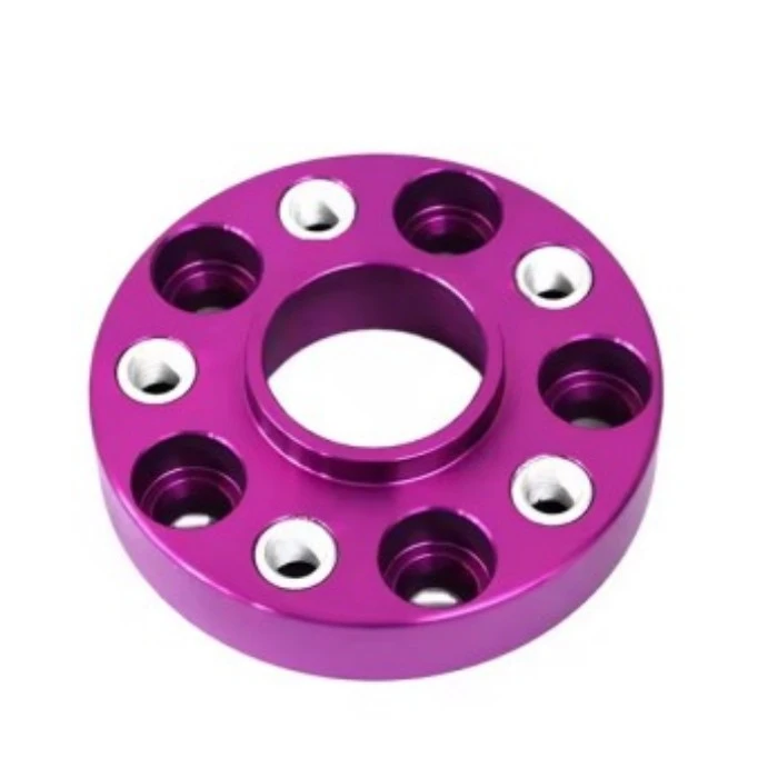
No. The spacer's inboard bore must fit the vehicle hub, its outboard pilot must fit the wheel center bore or approved centering arrangement, and both mounting faces must sit flat. A visible lip alone does not prove those interfaces match.
Are lug-centric wheel spacers always unsafe?
No universal verdict applies to every design. A lug-centered assembly must be engineered and installed for that centering method with the correct fastener seats, sequence and torque. A generic multi-pattern spacer should not be assumed compatible merely because its holes line up.
Will a hub-centric spacer always eliminate vibration?
No. Correct hub registration removes one possible centering error. Tire imbalance, wheel runout, contamination, damaged mounting faces, incorrect hardware and other vehicle faults can still cause vibration.
What dimensions define a hub-centric spacer?
At minimum, record the vehicle hub pilot diameter and height, spacer inboard bore and relief, spacer outboard pilot diameter and height, wheel center bore and chamfer, PCD, thickness and the complete fastener specification.
Can a hub center ring fix the wrong spacer bore?
A ring may be part of an approved wheel-centering arrangement when an aftermarket wheel has a larger center bore. It does not correct a spacer whose vehicle-side bore, lip geometry or mounting-face clearance is wrong.
Send the four centering interfaces
Include the hub pilot, spacer inboard bore, spacer outboard pilot and wheel center bore, plus heights and chamfers. A drawing or measured worksheet is more useful than the word "hub-centric" alone.
Safety note: This article explains centering concepts and inspection logic. It does not approve a spacer for a vehicle. Use application-specific instructions and have a qualified automotive professional resolve any uncertainty about fitment, hardware, torque or local road requirements.